
Began rough docking some of the left over maple material that will be used for the edging for the top cabinet panel. Not all of this will be used but I figured it would be best to just dress the faces than cut off what I needed.

Dressing the faces of the wenge timber. Again I will not be using this whole piece. I will just rip the board down to what I needed the left over sections will end up being used for something else in the project.

The maple chips out his due to the alternating grain structure. I Only dressed the rough faces off and left as much of the thickness as I could since I knew this was going to do this. The chip out sections will be taken out after sending it through the wide belt sander.

Ended up just sanding the pieces till the chip out sections went away before needing to rip the boards down for the small parts ie edging and molding parts.

Ripping down the wenge for the top molding parts and ripping down the maple for the edging sections. All the parts are over sized and will be sanded down through the wide belt sander. I have over sized everything so I was able to remove the rip saw marks and any chip out sections.

Edging strips sanded down and are now ready to be mitered than glue to the top panel.

Edgings mitered now ready to be glued to the panel, just doing a dry run to make sure that everything goes together well.


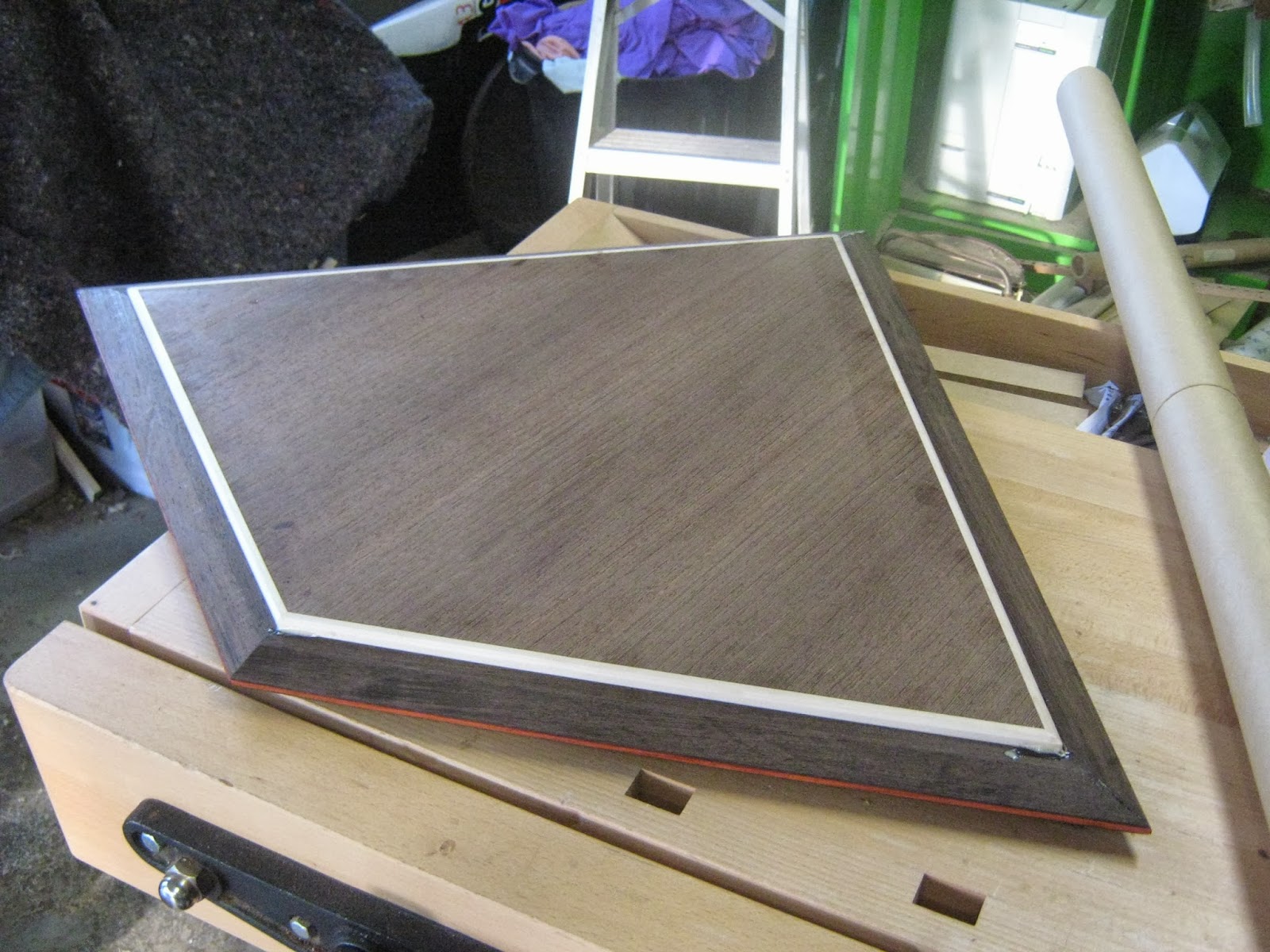
Edgings attached to the panel. Since its a difficult shape I just used the painters tape to act as a clamp to hold the edgings to the panel. I ended up using tight bond 3. This will be left for about 2 hours before removing the tape.
Making top molding sections.

Began making the rebates for the top molding sections. I placed down a 3mm MDF base to prevent the off cuts from falling down into the saw blade cavity. I wanted to keep the off cuts due to it being wenge and its quite expensive. These off cuts I probably wont be using for this project but will be used for other projects down the track.
I decided to change the rebates a bit instead of the rebates being 21mm wide I made them 15mm wide. There was 2 rebates top rebate for the top panel and the bottom rebate for the top carcass panel to sit into.

These strips are the off cut sections from the rebate. This is what would have been lost if I decided to rebate it on the upside down router or spindle molder or hand router.

Set up the upside down router to clean out the rest of the rebate.

Before making the shampher I made the 3mm deep stringy inlay rebate first. This is because if I decided to do it after doing the shampher I would have lost a lot of surface area on the rip fence and could have had a chance of damaging the stringy inlay rebate.
The shampher rebate was 64 deg. This meant that I had to tilt the saw blade to 26 deg. In my original designs the profile on the moldings was going to be a shallow concave curve. I decided to steer away from this since I would have to get a custom cutter made for it which would cost too much.
I also wanted to use the off cuts from the shampher as well. This would be used for shallow inlay strips for another project.
To make the shampher the molding the molding had to be placed through the saw upwards not on its side. The first shampher was easy it was the second shampher that was a bit hard since there was limited surface area for the molding to sit up on the rip fence. I had to get some one to tail out to make sure the molding didn't tilt when exiting onto the out feed section.
The blade was raised to 50mm and the rip fence was moved out to 36mm.


Moldings finished. The next step for these is to have the strong inlay glued into the rebate housing than have them sanded up than mitered. I will have to make a jig for this to sit in when making the miters. This is because to get a correct accurate cut I need to increase the surface area so there will be no rock.


Planing down the edgings for the top cabinet panel. I also used the card scraper to get a finer finish especially in the areas that had heaps of alternating grain. After this the edgings will have 45 deg bevel on them to break the edge.

Made a mistake with the top molding. The rebate is too deep. The top carcass panel (bottom mold location) needs to be sticking out of the mold by 4mm at the moment it is only sticking out by 1mm. To fix this will mean I will just have to make some 3mm ash striping that will sit in the rebate to pack it out. This 3mm rebate you will never see. It will be best to glue it down into the rebate before making the miters.

What its meant to look like.


I was making some alterations to the bottom molding. I had not finished designing the bottom molding due to maybe needing it to be wider than the top molding.
I decided on having the mold about 10mm wider than the top. I made the rebate wider since I needed more support with the bottom old compared to the top. The top mold rebate was 15mm wide where the bottom mold rebate was 20mm wide.
The bottom mold step after the rebate is 15mm where the top mold is only 10mm. I was thinking of extending this mold out by 10mm but decided not to. I decided not too since it would interfere with the fold section of the front door flaps. Also it looked to bulky and extended away from the cabinet too much. You noticed this heaps more so on the side sections and also at the front corner section where the front mold and the side mold meet to create the 72 deg mold angle. Having it 10mm wider from the internal diagonal point to the external point on the mold would be around the 100mm mark.
I was thinking I was going to have to extend it for extra support for when the front door flap rests on it.

The top mold had two rebates one for the top carcass panel to sit in and the other for the top cabinet panel to sit in. The bottom mold only needed to have one rebate which is what the base was going to sit into.

Ripping the wenge into smaller sections to than be further machined down for the top molds.

Cut into pieces for the front molds and side molds. These would be further machined down at tafe

Dressing the faces and the edges on the thicknesser. I wanted to keep these molds the same thickness as the top molds which was 24mm. These molds were going to be 54mm wide where the top molds are 44mm wide.


Made the stop cuts in the molds for the rebates on the panel saw. The rebates for the bottom molds were going to be the same depth as the top molds which was 9mm.

Like what I did with the top molds I had to place down an MDF base mask to prevent any of the wenge off cuts from getting stuck down in the saw blade cavity. I wanted to keep these off cuts which I could use for other things in this project or for another completely different project. Basically reducing the waste since wenge is expensive.

Made the stringy inlay rebates which were the same as the top molds. These stringy inlay rebates were 3.2mm wide (width of panel saw blade) and 3mm deep.

Making the 66 deg shampfer on the molds for the top and bottom. This meant tilting the blade to 24 deg. The off cut from making the angle was also kept which I would use for some inlay sections for another project.

The molds are now ready to have the stringy inlay placed into it than mitered.

Dressing down one face and one edge of the paduke slab I have. I only want to be slicing off pieces from the edges. I want to try and limit as much as waste as possible when using this timber since its quite expensive. Plus I don't want to have all faces exposed to the elements due to the oxidization in making the timber go darker.

Comes up with a very bright fluro red/ orange colour. This will darken though in the next day or two.

Ripping off a 5mm thick strip from the ends on the band saw using the T fence. The one dressed face and edge is so I can obtain a square even cut.

I than further cut this 5 mm strip into smaller 4mm strips. This paduke will be used for the stringy inlay sections for the molds and the drawer box lids and bases.

Making a jig to properly hold the molds when coming to mitering them on the saw.

Sanding the paduke strips down through the drum sander. I went over size a bit since I was not sure how paduke machined since I had not work with it before. Its a little bit like wenge where it sands up and machines easily but its a lot more brittle than the wenge. I had a lot of the stringy inlay strips break on me.

I cut the stringy inlay strips to size with my japanese hand saw.

Placed the inlay bits into the rebates and awaiting to be glued in.

The thing with stringy inlay is that you want a relatively tight fit where you don't need clamps. Some jobs when using stringy inlay you wont be able to get clamps to it.
You want about .1-.2mm of play between the stringy inlay and the rebate of the mold.
I placed the glue (tight bond 3) into the rebate with a small paint brush. A very small brush like the ones you would use for toy models. The paduke is very brittle so you don't want to knock the inlay in with a mallet. I found using a burnisher to press it in work really well. It only works if you have made the joint snug.

Some of the stringy inlay sections broke in half before even putting into the rebates. I made sure to glue the pieces in where the brake point happened so when cleaned up you would not even notice the break point.

Some molds did need clamps since the stringy inlay pieces were a bit bowed and were springing out of the rebate.

molds drying. This will be left alone for about 2 hours for the glue to cure.

Making the rest of the miter mold jig. Glued two pieces of mdf together with melamine glue (AV 56). One of the pieces was smaller in width so when glue together it would create a rebate at one end. This rebate is where the molds rebate would sit into creating support to it when being miter on the saw.
I would be building toggle clamps into the jig. I did not put much effort into this jig since when the miter cut is being made for the mold you would be cutting into the jig as well which would be acting also as a grain break point as well.

Clamped up two. Scored the glue faces before clamping up to create a better bonding surface.

Mitering the molds the front two molds will be 65 deg each. the side miters will be 36 deg each and the back miters made to 43 deg each.

Mitering the top molds there was enough comfortable surface area so I did not need to use the jig I was making. I just used the jig base to bump the mold piece further out so I could make the cut on my bench saw. The bench saw has limitations due to the depth of the sliding table.
Next time when doing this I would clamp in the stringy inlay when the mold is already miter and attached to the base.

Taped the molds around the base to see how well they came together. One of the molds was just cut 1mm to short which than made a gap. This can easily be fixed but will result in me having to cut some of the front rebate section off at the base only about .5mm on each side so nothing major. Besides that mistake the joints were very clean and quite accurate.

The molds were going to be a bit difficult to attach to the base in the manner I wanted them to be attached. I did not want to screw them to the base since it would look messy under neath and I'm trying to limit the amount of metal components I place with the piece.
I had thought about making dowel hole connections but this would mean that everything would need to be spot on with in the .5mm mark. In stead of using dowels I decided on using splines. This would make things a lot easier and would give me a bit of play to make the connection points more accurate in assembly.
I made a spline rebate in the middle of the mold (3.2mm wide, saw blade width) and 10mm deep. The other spline rebate would only be going into the base by 5mm deep so it will not effect the dowel hole joints for the sides.
To make this spline rebate on the panel saw I just set the fence to 8.4mm away from the saw blade. ( 20mm width of rebate - 3.2mm= 16.8mm, 16.8mm/2 = 8.4mm.
To get the dept I had to plus 10mm (depth of spline rebate) to the depth of the mold rebate which was 9mm. This meant setting the saw blade height to 19mm.
I was also talking to my teachers at tafe about a further connection point in the molds. Originally in my designs I was going to use splines in the miter joints which would create little arrow shapes. With discussion with one of my past teachers we decided that this would make the mold too messy. Instead the miter spline would be located into the middle point of the stringy inlay.
The mitre spline would be paduke as well. The only difference you would be able to pick up would be the end grain. My teacher also suggested to make this miter spline 2mm in thickness. The stringy inlay is 3mm wide so there would be .5mm offset on each side of the miter spine.
Placing the miter spine here would make things a lot stronger increasing the long grain surface area.

The floating tenon would not be needed since the miter spline in the stringy inlay section would be doing a good enough job.

The arrow splines would take away the simple neat look from the wenge molds and would make things messy also I would be making things a lot harder for my self.

Clean up and shaping would also be annoying as well.

So from the top you would see an arrowed shaped piece of paduke.

I had to glue down some ash packing into the bottom rebate section since it was too deep. The top carcass panel had to sit 4mm out of it. At the moment it was only sitting 1mm out of it. I had to fix this if I left it it would mean that the doors would not fit in properly.

Like the bottom molds the top molds would also have spline connections to help connect the molds to the top panel and the top carcass panel.

I did not want to make the spline rebates into the edgings as this would create a weak joint. The spline rebates were done on the circular saw they were 4mm wide and 5mm deep. I cut to the very ends which meant that the slits had to be 5mm deep so they would not show on the edges where the edgings poke out from the moldings rebate from the panel.
I could have made stop sections and made it deep but the splines did not need to be really deep they merely are just being used as a locaters.


Cutting the spline rebates on the panel saw.

Gluing down the 4mm pack strip into the mold. I used tight bond 3 glue.

Clamped up and left for 2 hours for glue to cure.


Unfortunately I had to make new spline rebates and glue packing strips into the old ones since I made a mistake and made the original spline rebates in the wrong spot.

Mitering the molds for the cabinet top panel. The molds were pretty much the same as the bottom ones except they were shorter in length, shorter in width and had an extra rebate which is what the top carcass panel would be located into.

I did not end up needing to use the jig that I made which was lucky since I did not bother putting that much effort into it. I thought that I was going to need it because there was not much surface area for it to sit on the table saw bench.
The miters were the same as the bottom, front miter being 65 deg side miters 36 deg and the back miter 43 deg.

I made sure to test the angles on scrap pieces first to get the right deg. I started off cutting the fronts at 65 deg taking off as least as possible. I than cut the back angles at 43 again like the front taking off as least as possible. This meant that the last angles to cut were the 36 deg which I could finish all the molds off at that angle.

Like the bottom I decided to attach the molds to the cabinet top by using spline rebates. The spline rebates were 4mm in thickness. The splines were 3.5mm, I only wanted a little snug fit.

I did a dry run and made sure that the top carcass panel underneath fitted as well. The negative spaced sections are where the sides would be located. These areas were about 20.5mm where the sides are 21mm. I was not bothered about this as I could easily tweak this so it would fit.
The top carcass panel would be connected to the molds with spline joinery as well same with the sides.

Dry run of top section in molds

To get more effective clamp pressure without having the molds tilt outwards causing a gap between it and the panel I decided to tape packing strips to the bottom rebates where the 'F' clamps would clamp to. This would create balanced clamp pressure. The only flat spot on the bottom of the molds is a 10mm step.

Did a dry run with the clamps. I needed to replace one of the splines since it was too loose.

I wanted a 5mm 45 deg bevel on the maple edging. I needed to place this bevel on first before gluing the panel into the molds. This is because of the router bearing. The bearing would be crashing into the mold.

Like the base it was a bit difficult to clamp at first. I had to use about 4 26mm MDF blocks to boost up the height of the panel so I could get the starter clamps under it to clamp the mold to the panel. I didnt use as much polyurethane glue as I used on the base. I cleaned most of the dry polyurethane off the base yet it was really annoying to clean up.
I started off clamping the corners first than I had to pick up the whole thing and place it on some work horses than continue to clamp the rest of the sections.
I actually found that this was a lot easier to clamp up than the base. The packing strips in the bottom rebate sections of the molds helped out heaps.


Clamped up with polyurethane glue and will be left for about 4 hours to allow for the glue to cure.

Was a bit happier with the miter joints for this one. There were some small gaps but these were located on the bottoms of the molds. The polyurethane glue expanded and covered these gaps any way.


Clamps taken off. The next step is to clean off the dried polyurethane glue.

Before doing a dry run with the doweled sides to the base I needed to drill out the expanded polyurethane glue from the dowel holes that had risen up from the bottom mold spline rebates.
No comments:
Post a Comment