
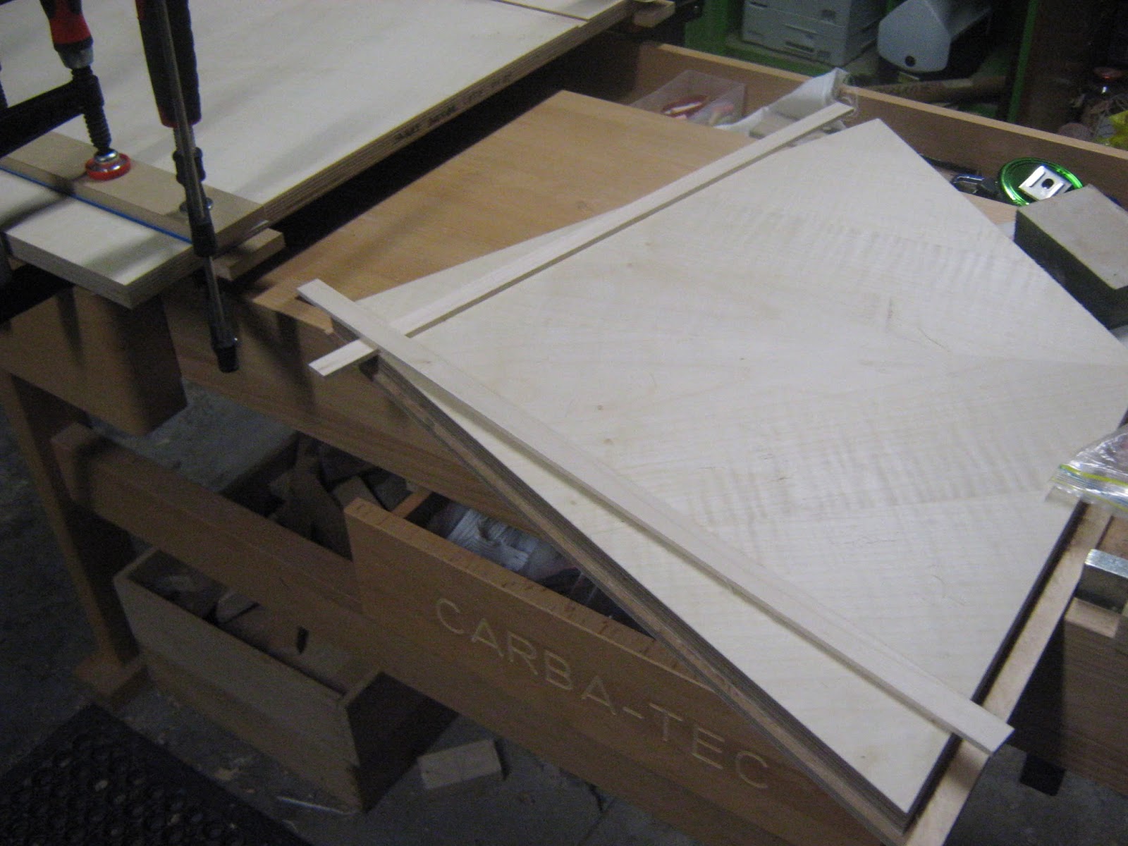
Drew out the rebate positioning for the edging in the base of the cabinet. Around the sides is maple edging that will connect up with the inlay edgings on the sides of the cabinet. Some of this inlay edging around the base will be sitting in the molding rebate which wont get seen only about 2mm. The edging is only 18mm high and 5mm in thickness.
As for the front rebate only a little bit of it gets covered with maple edging. 2mm for the internal bottom and 2mm for the internal front of the rebate. This is merely to just cover up the plywood edging. This rebate section is where the hinges for the front door flaps are going. Also the bottom of the rebate also acts as a ledge for the doors to sit on when folded down.
To make sure the measurements added up to drawings for the front rebate I had to cut the rebate 2mm deeper and 2mm wider to account for the added 2mm edgings.

Doing test cuts on some scrap mdf. I needed the blade depth to be around the 18mm mark. But first I needed to do a cut on some thiner stuff to make sure that the blade was running at 90 deg.

Test cut to 18mm.

Making stop cuts on the saw onto the cabinet base on the router cutting station.

Cuts placed on the front section of the cabinet base.

Removing the waste with the saw. I do have a router but it only has one speed and doesn't have a dust port for it which I tend to avoid using it if I can it is a old one. These rough sections will be cleaned out with the hand chisel.

Main waste sections removed from the front rebate section.


Cuts made for the side edging sections.

Time to clean out the rebate sections by paring out the waste with the chisel and brass mallet. I machined a 7mm thick piece of timber to act as support for the chisel to rest on when paring out the waste in the rebate. I used the veneer since I went below the 7mm mark a little bit. This was merely to just pack it up.
I clamped a sqaure piece of timber to the top which would act as another straight support section for the chisel to rest up against when cleaning the bottom part of the back of the rebate.

Clamped down the front support piece of timber with clamps since it was flexing up a bit plus so it would not move and I would have more control with cleaning the rebates. I also clamped down the back part of the cabinet base to the work bench to prevent that from moving as well.

There is a little bit of bowing in the cabinet base so to clean the rebate properly I had to clamp down the middle of it so the rebate would rest to the proper level with the timber piece.

Cleaning out the side rebate sections for the side edging.

Edging rebates cleaned out and ready to the the edgings glued in.


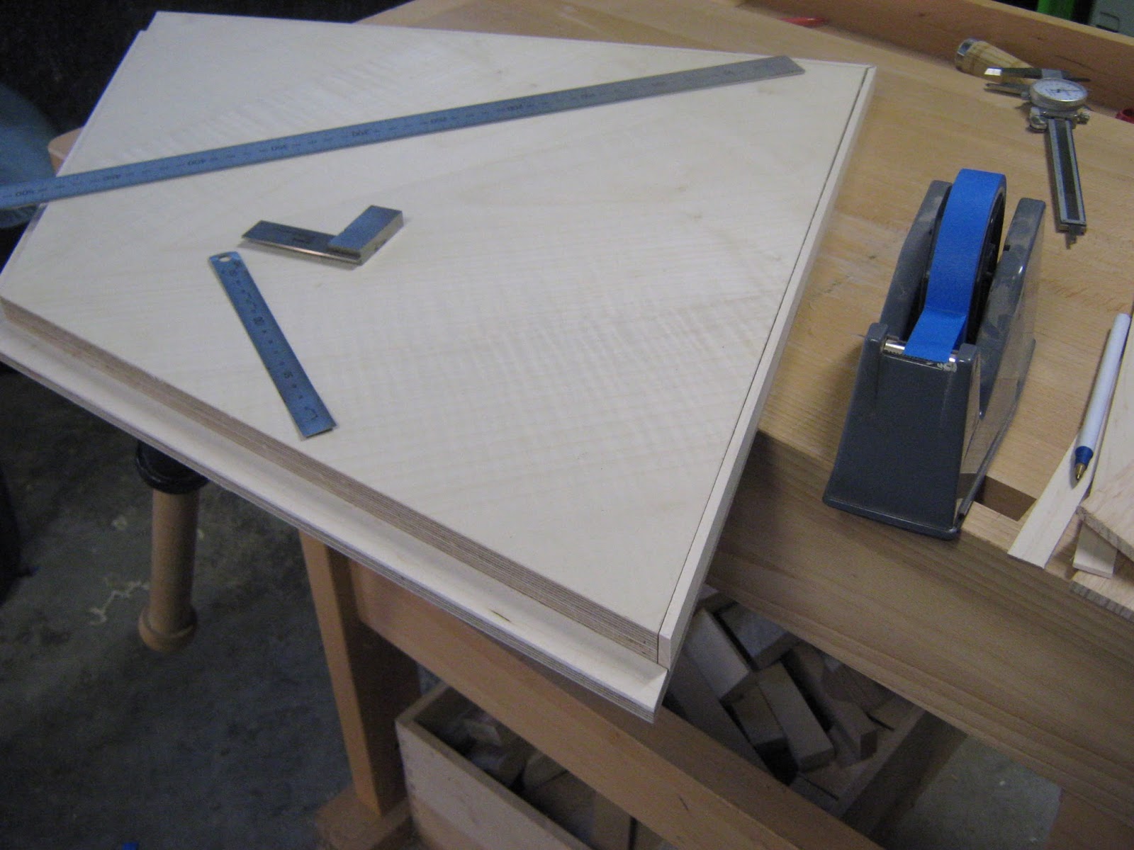
The rebates were a little bit out after checking it with the tiny square I have. Been a while since using hand tools.

Began sanding the edging strips for the cabinet base for the sides and for the front rebate. I wanted the edgings for the sides to just slightly sit over the panel (about .5mm) which I will clean up with a spoke shave and cabinet scraper.

Now to sand the edgings for the rebates had to be done in a specific way. I needed to sand the width of the bottom pieces first than sand down to their finished thickness. The width I only wanted to it to hang over the rebate by about .5mm. Once sanded down to finished thickness I than sanded down the width of the top piece, again only wanting to sit about .5mm from the base. After this I could than sand down to finished thickness which was 2mm.
These edgings are now ready to be mitered and glued in.

Cut a test piece for the front bottom edging. This angle is at 130 deg so both of the edgings had to be cut at 65 deg.

I set the cross cutting fence to 65 deg. Again with the other edgings that I have been doing that require angles I roughly set up to where the angle is than do final tweaking after seeing that the test edging was like when I have made the first cut.

I used a scrap piece of timber to act as a blow out prevention. Since the edging is only 2mm it can split really easily.

Testing to see how the joint was. Once I was happy with the middle miter joint it was time to cut the ends. These ends had to be flush with the sides at a 72 deg angle.

Gluing in the edging on edge clamped down and applying the glue to the next rebate section for the other side of edging.

Both edges clamped down and will be clamped down for about 2 hours for the glue to cure. I used tight bond 3 for this.

The middle point was pressing up a bit so I just used a small quick grip clamp. Normally you would just use quick grip clamps for all this edges since heaps of pressure is not need only light pressure. Its just I don't have many of these light pressure clamps.
Cutting the angles for the side edgings. The front needed to be cut at 72 deg where the back had to be cut at 43 deg. the two edgings at the back had to make an angle of 86 deg.

Angles are cut on the side edgings and now ready to be glued to the base. I place painters tape on the top face section near the side where the edgings were to be placed to prevent any glue going onto the veneer. This would make cleaning up later on so much easier.

Applying the glue to the first side edging. I just used a very small brush. The glue I used was tight bond 3 again.

I used painters tape to act as a clamp. Due to the shape of the base I could not use 'F' clamps or sach clamps unless I made a jig.

Cutting the last of the front edging. This front edging would be cover the front face of the rebate. The middle point of the edging had to be at 130 deg ( 65 deg for both edgings) just like the bottom edging. The sides also had to be cut at 72 deg. I did this edging last because I wanted it to cover the end grain face of the side edgings.

I placed painters tape down on the bottom edgings face and the top veneer face to prevent glue doing on it when clamping up the last of the edging.

Used baking paper and a piece of timber that acted as a caul and pressed down the edgings. I also used painters tape that acted as a clamp providing front pressure. The clamps are acting as top pressure.


Clamped up and will be left for 2 hours. Before doing any of the dowel hole connections for the sides and middle division also hinge holes. some of the surfaces need to be cleaned down with the spoke shave and cabinet scraper.

I began cleaning the edges of the base where I had stuck in the edging strips. I need to get all these sections cleaned up and square before making the dowel hole connections on the pedestal drill. The streps were not that high and did not require using a spoke shave just a cabinet scraper. I just had to sharpen it again to make sure it was really sharp.

This scrap piece of MDF was used to make sure that the edging was totally flat and square. Some of the edges were a little bit off. But what I will be doing is placing a slight aris on it only with the side edging. This will just break the edge and make things needed.
I was also checking with my engineer square as well to make sure that I was on the right track.

I also needed to make sure that the edging was sitting level with the end face edge of the plywood panel. Most of this section will be sitting in the molding that will be surround the cabinet.

I also needed to clean the fronts as well.

Marking out the dowel hole placement. The center of the dowel holes need to be 10.5mm in from the edge. 10.5 *2 = 21mm ( thickness of sides) To make sure that 10.5mm was on both sides I set up the marking gauge to 10.5mm.
Each side was to have 5 dowels.

My drawings I choose to use 10mm diameter dowels. Traditionally a dowel joint is like a tenon joint where the thickness of it will be determined by the thickness of the material that the joint is apart of. Usually the joint is 1/3 of the thickness of the material.
The sides are quite heavy and using a thicker dowel would give me more surface area in glue bonding. Although using a 10mm dowel compared to a 8mm dowel it leaves about 1mm between the finished edging of the dowel hole to the starting point of the edging which is glue to the panel.
The edging is secured to the panel quite well ( I used tight bond 3)
I decided on using the 10mm diameter dowel.

I did a test drill first on some scrap veneered MDF. I set up a fence to insure that I was going to get the 10.5mm from the center point of the dowel hole to the edge of the panel. Having a line on the fence would make things a lot easier to line up the drawn out dowel joints to bore.
Before drilling the holes I taped in the center points with a fostner drill bit which would act as a locater.
In my drawings I had decided on using 15mm deep holes. I decided to change this and bring the depth to 21mm. This would leave 5mm from the base of the hole to the bottom of the panel. This would give more more glue total surface area for the dowel into the base.

I was quite happy with the joints as everything was matching up. I was probably out in some sections by about .05mm which I think is quite bloody awesome.

Marking out the dowel connection holes for the drawer division. These holes were 6mm in diameter and were going to be 20mm deep. Both ends 25mm in and the rest 118mm spaced out. In total there are 5 holes. In my work drawings I was going to use 1 spline. This would have been easier to machine but more difficult to assemble at the end. Even though the boring of the dowel holes had to be way more accurate it would make things a lot easier at the end in assembly.

Making dowel holes on the pedestal drill.

Did a dry run and things seem to fit together quite well.

I did a test drill hole to get the right height.

It was a very difficult shape to try and borer a hole into. It would have been better if I drilled the holes in before the edging was added.
I had to use 'F' clamps to get the entire base flat. The drill holes have to be very accurate.

Like with the doors once each drill hole was made the job had to be un clamped than set up again to make the next hole.
To get the right depth I had to machine a few different stop blocks that were positioned underneath to get the right drilling depth which was 11mm.

To get more support I had to use more clamps. The very end holes were the most annoying. I had to get someone else to help me to clamp it down since the piece was too awkward as most of th was hanging off the drilling table.

I had to change to drill bit that I was originally using for the doors for a longer one so I cold obtain the correct drilling depth.

Drilling the end holes meant I had to use a set up like this to get the base to sit really flat. Placing a clamp in the middle of the piece of timber puts pressure on both the packer to the table and to the board.

Drilling the other side.

Band sawing down some maple stock to make new front edgings to cover over the old front edgings for where the ZYSA hinges are. I had to add in this packer due to the modifications that I needed to make due to the front doors being pushed further out due to some parts being made smaller due to mistakes.
I band sawed the edges down to 18mm wide and 10mm thick.

Machined band saw marks off taking the edgings down to 17mm in width and 9mm in thickness.
Even with the thicknesser slowed down to speed one and placing the edgings on an angle they still split out a fair bit due to the alternating grain structure. Luckily I over sized everything which I would be taking it down to its finished dimensions through my drum sander.
The finished dimensions are 16mm wide and 6mm in thickness.

The edgings were made over size since they will need to be mitered later on. I had to mark out all the drill holes that needed to be made so they would line up with the old ones. Since edgings would be placed over the old ones I would be packing the holes in so they holes are taken back to 11mm in depth.
As for the old maple edging I will be making a trench to remove the top layer about 2mm than add in a paduke stingy inlay strip to make it look like its part of the design. Leaving it would make it look too messy making it look like a mistake has been made. ( which there has been)

Marked the tops and bottoms also front back and inside edge to outside edge. Once the holes are made these can only go in one placement.

I used the same drill bit that 1 used last time on the horizontal borer due to their being a slight mirco wobble.
I drilled the holes 2mm away from the top edge, spaced out 89mm and 50mm from the inside edge to 53mm from the outside edge
No comments:
Post a Comment