This post is the most up to date posting of the door construction.
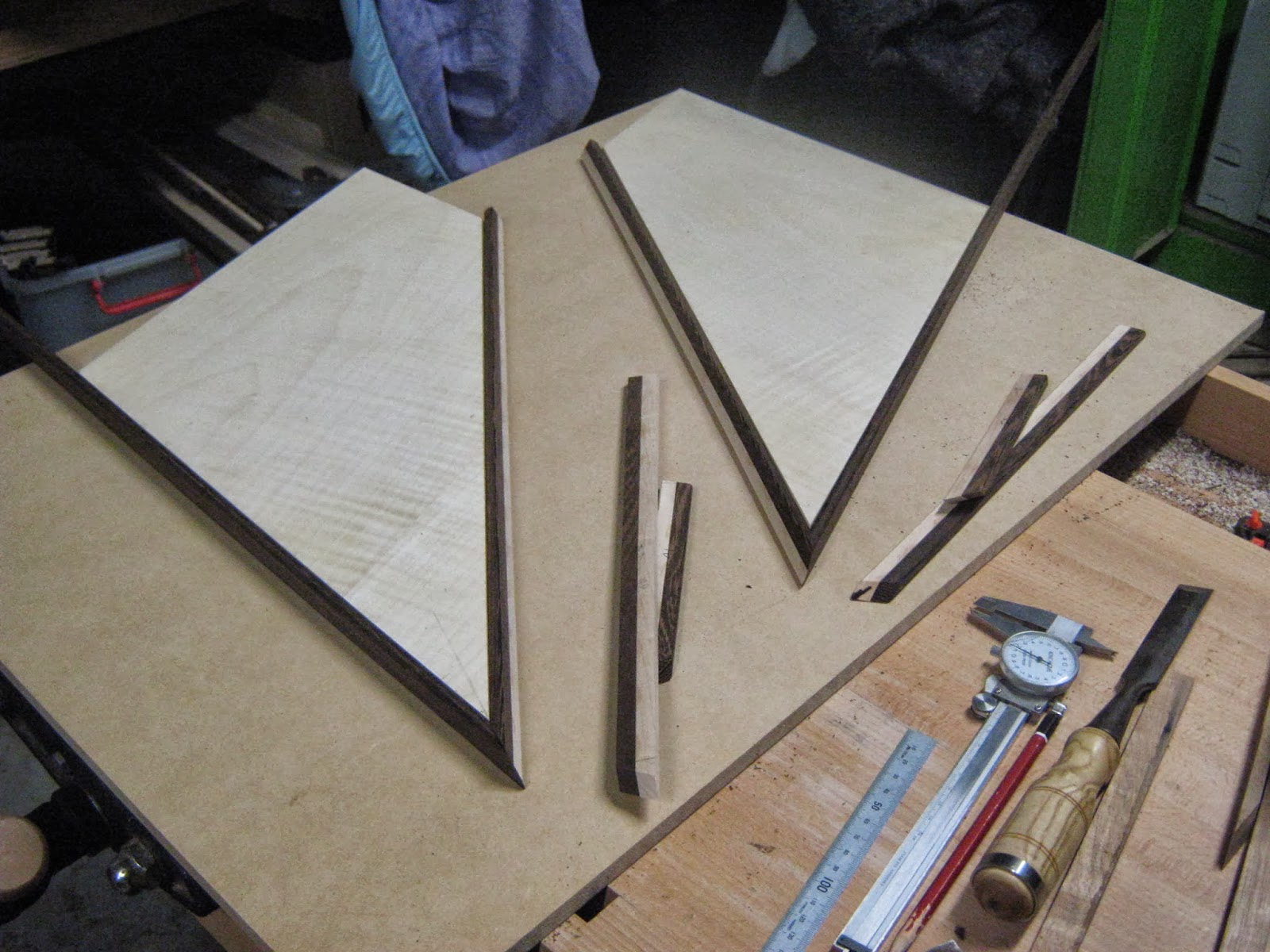
Started to the compound angles for the edgings for the doors. There requires a lot of patience with this as it can not be rushed and there are a lot of test cuts that are required before doing the final cut on the laminated wenge/ maple edging.
You are going to get over hang between the two edges because with the joint there is a flat 90 deg edge running into a 25 deg slanted edge. Also the edging for the 25 deg slant is about 17.8mm. Where the straight panel edged face is 16mm. So this means there is going to be some over hang in the joint because the edgings have to be different widths.
What I will be doing here when the edgings are glued down and dry is making a feature out of it. I will be planning down the over hang and making sort of an angled feature with it. The middle point of the edgings where the middle of the lamination is wont line up with, but I'm not too fust with this since im placing a paduke miter spline here. The lamination joint is only offs setted from one another on these types of joints where there is a 90 deg slat edge face running into a 25 deg slanted face.
Bottom outer miter of front door flat.
The back door miters for the bottom section will also be the same as this as well.
These two pics are from the bottom outside corner of the back doors. Some of the miters are harder to achieve than others since ( like this one) one edge is a flat 90 deg edge where its corresponding edge is on a 25 deg slant.
Even though the miter is 45 deg its actually not cut at 45 deg. The miter is set at 48.5 deg for the bottom mitered edge. As for the beveled angle ( saw tilt) it is set at 17 deg. The side edge which is on the 25 deg slant is set to a 45 deg miter and 0 deg bevel.
This required some testing to see if it was going to work first on some scrap. I machined some scrap that was the same dimensions as the edging.
Now every miter will be different not just in the deg set up for the actual miter and bevel but also how it is loaded and cut onto the drop saw.
Some edgings required to be either cut on the left or right, flipped over or having the whole drop saw set to the other side but still set to the same deg specifications.
With all the cuts I used a scrap piece of MDF to act as a breaking point to prevent blow out from the back of the edgings. Also this prevented kick back as well. The main prevention of kick back is to start the saw up to max speed pull saw right out on slide bar than push into job. Once cut is made you want to stop the saw but not pulling away the cut part. Only pull away when the saw blade has stopped. The reason you do this is to obtain a clean cut some times pulling away can cause small ripples or nicks on the cut line due to mirco wobbles in blade.
In one of my other posts ( drawer box construction 2) I have posted up a link on a safety run through on the festool kapex 120 drop saw by the wood whisper he goes into more detail than me with best safety tips on using this saw. If you don't have this saw his safety tips can be applied to any other drop saw.
The top miter section of the doors.
This top miter both of the edges were being placed on a 25 deg slant. The miter angle set up was 51.5 deg and the bevel was set to 19 deg. Now I did not need to move the drop saw to the left side set up as all I had to do was make the cut for one of the edges on the left than make the next cut of the second edging on the other side.
The over all angle ( internal) for the two edgings was 72 deg. So the miter was being shown at 36 deg but the actual miter angle set for the saw had to be 51.5 deg. This is what can be confusing when doing compound angles.
I had to remove the large fences on the drop saw since they were getting in the way when cutting the compound angles this was heavily due to the plastic rubber dust hood get caught on it when making cuts.
Doing the compound for the top section of the doors. This compound angle is the same for the front top door flap sections and the back doors.
I did tests first before machining the real thing.
Used a backing block to prevent blow out since the edgings were quite delicate especially the wenge.
For most of the cuts for the edges after obtaining the correct angles I used a fake bottom plate this allowed me to see where the finished cut was going to be from the blade. It allowed me to creep in the edging to get a more precise cut.
I found it was best to cut 1mm over from finished internal miter length just encase it slightly slipped which sadly happened to some of the edgings.
This edging was the most warped out of all of them and would prove some difficulty in gluing it to the panel also obtaining the correct internal miter shoulder length.
The top compound miter for the top front door flap was the same as the back door top section.
The very top compound angle set up was 51.5 deg for the miter and 19 deg for the bevel.
The second top compound miter angle for the back door was 20.5 deg for the miter and 9 deg for the bevel. The front door flaps were slightly a bit out miter being 19.5 deg and the bevel being 8.5 deg.
In between cutting the edgings I placed the doors and edgings under weight as it has been very hot and I want to limit the bowing.
Tests cuts first to make sure that the miter joints go together well.
For the left door the bevel angle needed to be 7 deg and the miter angle needed to be 13.5 deg. As for the right door it was slightly out and the bevel needed to be 6.5 deg and the miter had to be 13.5 deg.
Doing tests first to make sure the joint goes together well before cutting the real thing.
The angle set ups for this compound angle for the bottom outer corner for the top front door flap is as follows.
Right door flap:
Left side (wenge/ maple laminated edge) miter 37 deg and the bevel 8.5 deg.
Right side ( solid wenge edge) miter 37 deg and bevel 22 deg.
For the left door it was just swapped around.
Solid wenge edging miter 37.5 deg and bevel angle 23 deg.
Maple/ wenge laminated edging miter 37.5 deg bevel 7.5 deg.
This is the left bottom section of the front door flap. These cuts are done on the left and right side of the blade for the right door they are reversed.
Two jigs were required in cutting the compound miter for this edging section. For the right top front door flap the 65 deg edging had to be cut on this jig.
The 90 deg edge would be used on the other jig to get the partnered miter. As for the left side top front door flap the edgings would be opposite.
This compound angle could not be cut on the drop saw it had to be cut on the sliding table saw.
The jig here starts at 60 deg on the miter than is bumped out a further ( ) on the miter.
This jig is a little bit dangerous. It would have worked better if I made a sled which would result in removing the whole cross cutting fence. But the thing was I was only cutting two angles so it was not worth it. The sled would move by having a piece of timber attached to it that would run in the trench in the saw table top.
This jig was also cut at 60 deg as well than set to further steeper angle. I used a screw to act as an adjuster allowing me to tweak the angle set up until I got to the angle I wanted.
I packed the jig up high enough so it would clear the cross cutting fence. This than required me to raise the saw blade to maximum height. The clamp holds the jig in place preventing it from tilting down.
Its very important that you have a break out block behind the edging when cutting it. Since the edge hangs out a bit the blade is putting a lot of tension on it and can cause major break out. I found it better to clamp down the break out block and also tape it to the edging. This meant that it limited the break out, created and created more support. You would need to cut into the break out block to achieve the cut on the edging.
It would also work better if I had a finer toothed blade and a sharper one but at the time I did not have either of these.
You would also have less break out issues if it was in a sled form as you would have more support with the edging when cutting it.
I had to cut out this section at the back since I had to alter the angle a little bit more in the jig and I needed an exit point for the rest of the edging to follow out. Luckily it just ran between the clamp pad and the clamp pole. When doing long edgings like this this is where it would have been better to make a sled, but like I said I was only making two cuts.
A lot easier in cutting on the opposite jig as there is a lot more support. I taped the edging with painters tape since I cold not put in a clamp block since the cross fence got in the way. Again a sled would also probably work better in this situation as well.
Just finished cutting the really acute angles for the top front door flaps.
Angles for this section went together quite well. Out of all the edgings this is the most acute miter.
inside view of top left front door flap.
outside view of top left front door flap.
out side view of back door.
inside of right back door.
Inside view of back doors.
outside view of back doors.
inside view of right bottom front door flap.
Out side view of right bottom front door flap.
inside view of right front door flap top and bottom sections put together.
outside view of right front door flap top and bottom sections put together.
Close up sections of the doors on all faces in dry run.
Out side sections of the doors.
Just finished the miters. Quite happy how they turned out besides some of them having little gaps. At the moment they are in a dry run. The maple faced sides are the insides of the doors.
Dry run of all doors in their closed postion. Was a good time to test the magnets in regards to their snap locations.
Dry run of the front door flaps in their opened folded out position.
Placing a aris on the panel edges and timber edges. Also sanded the glue faces of the panel edges and timber edges to give a better glue bond surface.
Just doing a last dry run with this door flap since some of the edgings were a little bowed. Plus I wanted to see what the edgings looked like to the panel. I had just sanded the edges of the panel creating a small aris. The edgings have a small aris on them as well on the inside and outside. I was basically creating a sort of shadow line.
Clamped down the edges to the front top right door flap.
Clamped up the edges to the back right door.
Gluing the edging to the right bottom front door flap. I began to run out of blue painters tape which resulted in me using masking tape. There were a few little gaps in the miters as some of the edging slipped when mitering it and I could not afford to replace them as I did not have the material to do so.
The outside edge was quite bowed this was more due to the maple section of the laminated edge. The main bowing was happening in the knotted section where the grain direction was changing in different directions.
I thought I was going to have heaps of problems with this but actually it went together quite easily. I decided to glue this piece onto the door last. I had to use peg clamps to prevent the edging from bowing up. I did a dry run first to see if I could do this.
Originally I was thinking that I was going to have to make small dowel locators that would hold the edging into place and prevent it from bowing up. These dowel locators would actually be BBQ skewers which I would cut down.
There had been some pretty hot days which made some of the edgings bowed this also made mitering them a bit difficult.
Finished clamping the edgings to the left back door it will be left like this for a couple of hours to allow for the glue to cure. The glue I used was tight bond 3.
Some of the edges are 90 deg and others are 65 deg. Some of the miters have two of these edges running into one another. This means that there is material over hang in the miter. The 90 deg edge is 16mm wide where as the 65 deg edge is 17.8mm wide so there is a chance of over hang.
The shaping gives off quite a nice sculptural look to it which adds a interesting design feature to the doors.
Shaped design feature on the side at the fold line between the top and bottom front door flap. You will see this feature when you look at the cabinet from the side.
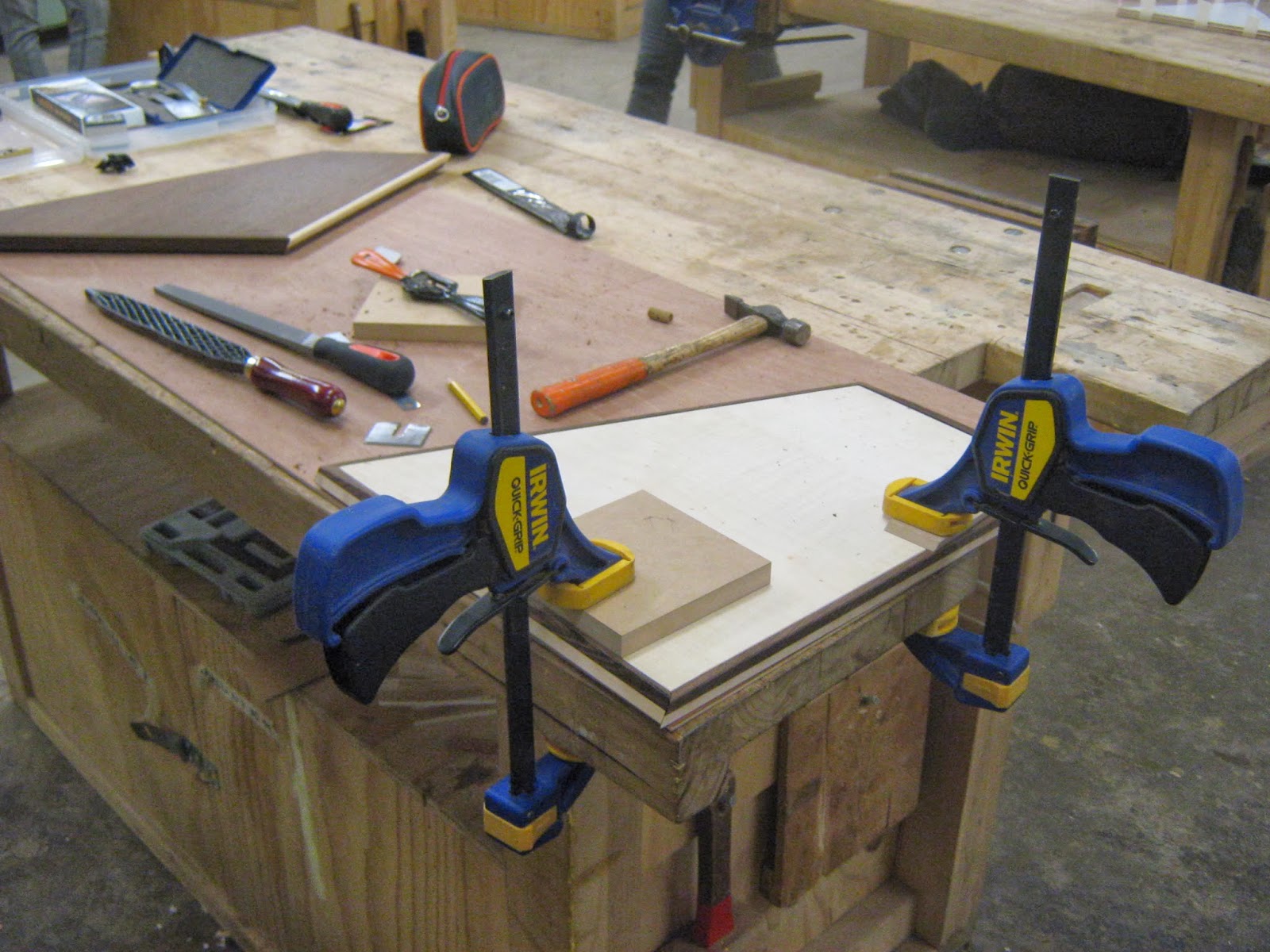
Found it easier to shape the parts while clamping them down to the work bench with the quick grip clamps.
The shaping consisted of using a spoke shave blade, japanese rasp, files and sand paper 240 grit.
Shaping the back doors only the top of the doors at the corners needed to be shaped on both the maple and wenge faces.
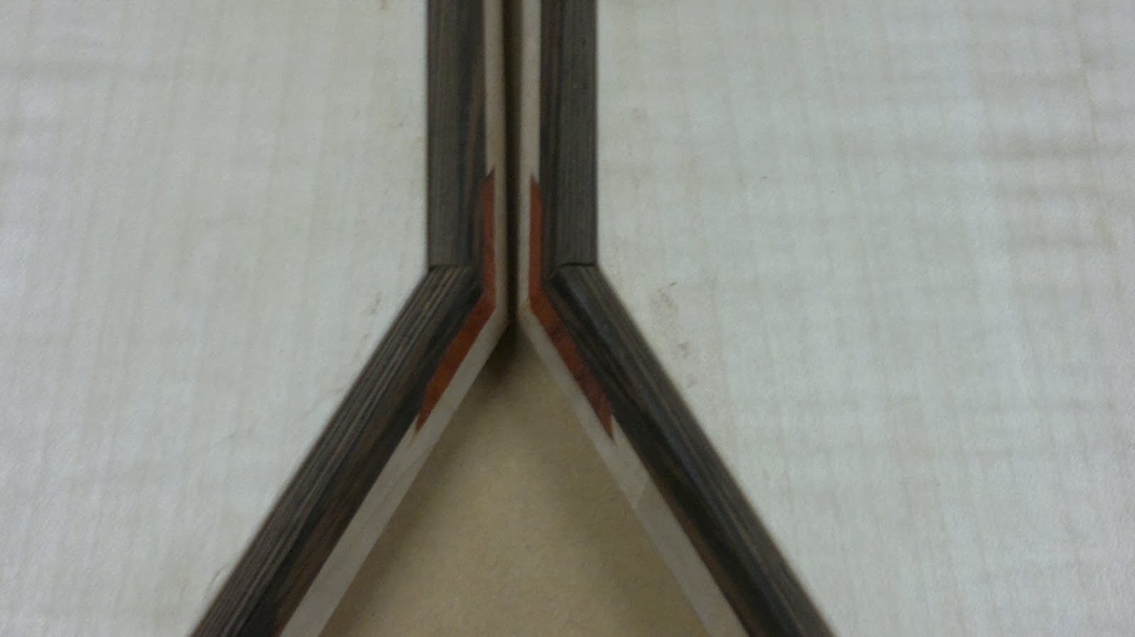
Where the miters meet for the 90 deg edging and 65 deg edging the middle of the laminated edges don't match up as they cant due to be different widths. This wont matter as the middle corner sections will be taken out when the miter spline grooves are made on the spindle molder.
Front door flaps all shaped but I have a feeling I'm going to have problems with the fold line edges were the ZYSA hinges are going.
I like how the bottom of the jointing doors creates a cool curved detail when shaping down the over hanged edging sections.
Due to the over hang between the edgings I needed to curved it to flatten it down. There was going to be a over hang regardless. This is because of the joining edges that made up the miter, one edging being 90 deg and the other 65 deg. The 90 deg panel edge was 16mm where as the 65 deg panel edge was 17.8mm.
These were the main sections I was concerned about with the ZYSA hinges when drilling the holes.
I wasn't quite happy with this edging since i damaged it a little bit, I tried to fix it but ended up making it worse. I decided on replacing it now where it was easy to do so.
Taping down the new edging that had to be replaced for the bottom inside section of the left door flap. I used tight 3 glue and this will need to sit for about 2 hours before taking it off.
Machining the ZYSA hinge holes
I would need to drill hinge holes into the base and the bottom of the bottom front door flap sections. The 2 mm offset needs to be to the maple faced side of the door ( back face). This would mean that the 2mm offset for the hinges in the base would need to be closer to the top face.
What I should have done is drilled the hinge holes into the base before gluing it to the molds.
A first I was thinking of using 3 holes. The original plans were 4 but I was thinking now that 3 would be better and four would be an over kill. I actually decided to go back to the 4 due to the weight of the door and also the strength of the magnets.
I moved the outer hinges closer in as I was planning on having miter splines and did not want these to come too close to the hinge holes.
Did tests first on some scrap pencil cedar. Pencil cedar is really soft so thats probaly why the hinges felt loose in the holes even though the screw adjusters were adjusted to their limits and opening the hinge more to make it tighter.
When machining the hinge holes all the doors had to be referenced to the work table face on the wenge veneer side face (outside face). This is because this is the flat face, the other face has the over hung edges due to the panel edge angles.
Due to the awkward shape I had to do each set up differently. I could not use a fence as a reference so I had to line up the drill bit to where I want to borer into. Before drilling I had to clamp down the door so it would not move.
The set depth stop on the horizontal borer is broken and is limited in positioning. I could not use the stop to stop up against the board so I had to use double sided tape and stick down a block that acted as a depth stop. I knew it would hit the right depth when the depth stop would hit this block.
The hinges were 11 mm long. In the parameter book it said to drill the hinge holes to 11mm deep. I drilled them to 12mm inside since on the fold line you would have oil build up not a 1mm but about a max of .5mm.
The holes were 10mm in diameter. It would have been better if I had a selection of drill bits that ranged from 9.6,9.7,9.8, 9.9 and so on.
It seemed like I was getting a micro wobble of about .1-.2mm as the hole was reading a bit differently. At first I thought I could use the imperial drill bit instead of the metric, the imperial was ranging around about 9.6mm. This didnt really work was way too tight. The reason why I was wanting to go smaller was because the test I did they seemed too loose, but when I drilled into the wenge/ plywood it was really tight.
So in this case it would have been better if I had a drill bit that was probably 10.1mm in diameter.
Drilling hinge holes for the top fold flap, left hand side.
A bit tight but goes in well. The key thing is you want a snug fit but not too tight where it is problematic to remove it.
Machining the hinge holes on the horizontal borer. This is the left top front fold part.
Only 2 of the hinges were showing up through the front face of the doors. This was the worst one. I'm not happy with this and will result in me removing the edge. Even though it seems like this has been a waste of time at least it has shown me that the fold line works. Although I may probably see if I can get the next size up.
I found with these hinges they were quite cumbersome and annoying to install, especially when you want to take them out you all most have to reck them to get them out.
They are quite tight even though the loosening screws are loosen out heaps to their max point. The only way of getting them out this wiggling the actual hinge mechanism with a pair of pliers.
To knock them in you gently need to tap them in with a nail punch. I think for next time when I make these hinge holes ill put felt on the pliers and nail punch to try and limit the amount of damage to the hinge. Also I will try and sand the in side of the hinge hole a bit just to bring it down by about .1mm
The 2mm offset needs to be towards the wenge face ( outside) this is so it folds open properly.
The folding movement works quite well. There is a little bit of movement but this is due to the magnets. Did not think they would be that powerful, thought that the hinges would hold it in place. Besides that quite happy how they fold just not happy that some of the hinge shows up on the front face due to the large aris added.
I should have done the hinges first before doing any of the arises, but ill know that for next time.
I wasn't too happy with these edges since some of the holes from the ZYSA hinges showed up a bit facing from the front. This was due to too much of an aris added to the edges. Totally forgot about that the hinge holes are offset 2mm from the outside edge. They need to be off set so the door flaps close properly.
I decided on removing the edges and making new ones. Surprising they came off pretty neatly. A good thing that I used tight bond 3 and not polyurethane glue.
Gluing in dowels into the hold hinge hole sections that went into the plywood panel. I used polyurethane glue for this.
Began cutting off the over hang dowel sections from the repair fold line panel edges on the front door flaps.
I cut these flush to the panel edge with the flexi Japanese hand saw.
Cutting compound edges to new wenge fold line edging.
Using the old jigs that I used before hand.
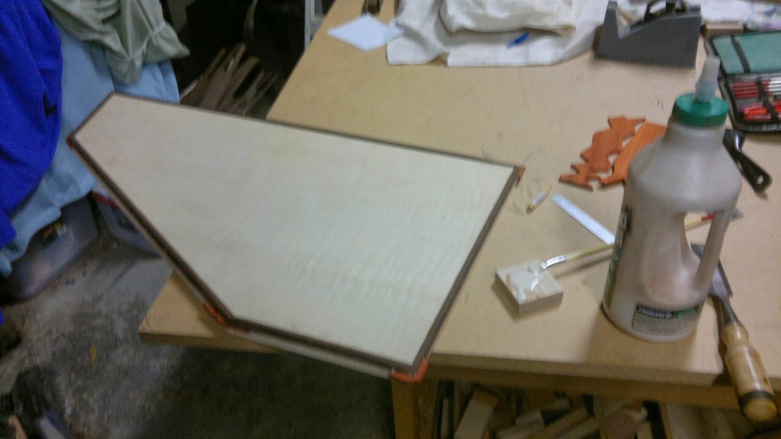
Glued the new edging to the top front right door flap panel with painters tape.
All edges glued to the panels with blue painters tape. Will leave this tape on for a couple of hours to let the glue cure. It has been quite a cold day and have decided to leave it a bit longer than standard one hour like I did before, even though it was a really hot day that day.
I sanded the inside edges and the glue face but not the outside edges. They will only get sanded when the ZYSA hinge holes are drilled. But only a light aris will be placed on these.
The doors now are ready to have the hinge holes placed into them. The over hung compound miter edgings will also be shaped when the hinge holes are placed in. This is something that I should have done at the start.
Drawing out all the locations for the ZYSA hinges not just in the fold line but also at the bottom of the front doors where they connect into the base.
Drilling the ZYSA hinge holes on the horizontal borer into the front door flap fold line sections and base sections.
Some of the doors were a bit awkward to clamp due to lack of clamping sections that would not inter fear with the sliding mechanism of the horizontal borer.
This meant that I ha to use a piece of timber as an extension clamp with a 'F' clamp secured to it.
Since the drill bit depth stopper could not be lowered further since it was broken I machined a stop block that was clamped at the bottom of the back of the borer. The lip of the table would hit the block when it had got to its finished drilling depth.
Each time a new drill hole had to be done a new set up had to be done the only things I didn't have the change were the depth of the holes and the offset of the holes on the edging.
The holes were 11 in depth. I had to consider also that the edges would have finish placed on them so if the holes were a bit lower than 11 than it would not matter. You just don't want it higher than 11,
Unfortunately some did get to this depth. This was because the glued in dowels to the repair sections broke out taking the holes back to its original depth. This will mean when coming to fit up I will have to pack in some pieces of veneer to pack it out.
Machining the next hinge hole sections for the front door flaps. These were for the bottom folding parts.
All hinge sections match up prob out by about .2-.3mm.
For the middle fold line section for the front door flaps the hinge holes had to be offset closer towards the wenge face ( outside face)
As for the hinges at the bottom of the front door flaps the offset had make the hinge hole more closer to the maple face ( inside face)
Drilling the bottom hinge holes for the front door bottom fold section. These holes will connect the bottom section of the door flaps to the base.
Hinge holes made now to drill the hinge partner holes into the base.
Miter splines
Working out the angles for the door miter sections and placing the reference angled lines onto the jig base.
This jig will be pretty much the same as the miter spline jig for the lids just bigger.
Each miter section will have a miter spline groove made into them. This will not just increase strength in the compound angle miter sections but will also be a decorative feature. Mainly its a decorative feature.
Like the smaller spline miter jig there will be edges for the door to rest up against. These edges are to hold the toggle clamps to press down the door and keep it in place whole machining. But mainly these edgings are used to position the door in the right angle so I'm able to obtain the correct spline groove.
Each spline groove will be a different depth but will roughly be the same length.
The edgings will also lower the chances of blow out.
I had to use the spindle moulder at tafe since the one at work was broken. The one at tafe I had to make a fake fence and gently move the cutter in to make a saw cavity. Having a saw cavity in a fake fence would decrease saw blade exposure and create more surface area for the jig to rest up against when making the miter grooves.
All the miter grooves were 4.5mm wide except for the top flat edge sections of the back doors and the bottom flat sections of the front door flaps.
The other grooves were 5.5mm wide. They needed to be bigger so they would make a clean visually connection between the laminated connection between the two mitered edges.
I had to do test cuts first to make sure I was obtaining the right spline length on each side of the edges. My aim was to get them to 20mm in length but I was not bothered heaps if it was slightly under or over.
Due to the protruding edgings on the maple faces due to the panel angled edges I could only run the doors on the wenge faces (outside face) this was the flat face.
Gluing in the paduke splines into the miter grooves. The glue I used was tight bond 3. I decided not to use the polyurethane this time since when using it for the drawer box lids it was too messy.
I cut the paduke splines on the scroll saw.
As for the middle connection miter between the two back doors I had to make them a bit wider so the two of them would be the same length. The angle I made the cut for these was wrong. I'm not too bothered that these are longer in length compared to the others as it creates sort of a central feature to it compared to the others.
I had to chisel out this extra section. When gluing in the spline I had to do it in two parts as this extra section wasn't following the same angle placement as the other section.
There were some little gaps so I filled them in with paduke dust and super glue.
Gluing in the rest of the paduke splines.
I used the flexi Japanese saw to remove the waste and clean down with a small spoke shave blade and a fine file. There still needs to be a few more touch ups but this wont be done till the big clean up when everything gets sanded.
Connection point between the two miter splines between the two back doors.
I'll have to make a few light modifications with some of the paduke splines seems like I did not machine them long enough for some and don't sit right visually especially the ones that are at the fold line on the front door flaps.
Cleaning off the over hang sections from the paduke miter splines. This was done with the flexi Japanese hand saw. The paduke splits out really easily its so brittle there were a few repair jobs that I had to do.
Modifications to hinge section for base of front door flap.