
Since this project is going to take donkeys years to make and I have limited time even though I'm running out of work till more machines come in and finances I have to keep pushing forward. I cant afford to have this stopping.
So I decided on working on the jig for the spline connection slits.
I did a few sketches of different kinds of jigs that would be useful. At the end I decided to go with this idea. Now with jig building no need to make it over complicated. Jigs need to be quick but still built to a good quality standard. Although in many cases it is important not to rush the jig as the more time you spend it the better the result will be. So really plan out your jig whether its through a sketch than dropping the idea into a program like auto cad or sketch or solid works or do a life scale drawing.
Run through the idea of the jig on how its going to work. Like furniture the jig needs to be ergonomically effective. Ie comfortable to use, not to heavy since you will be using it often easy to adjust etc etc.
I just came up with the sketch in my little sketch book. I tend to keep this with me where ever I go. You always need to be prepared as you don't know when you will get a great idea. I even keep this next to my bed just in case I wake up during the night and have an idea whether its a word, sentence or small sketch.

Like for example for being ergonomically effective. The jig really needs to have a handle to make it easy to push against the saw bench fence to make the cuts. As well with a handle also makes things safer since it keeps hands again away from saw. The left hand will be used on the handle to push jig where the right hand will be used to ensure that the jig is running up against the saw fence.
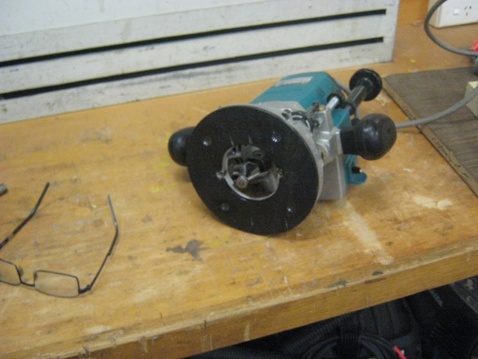
I decided on basing my handle on a circular saw handle since its comfortable to use and already ergonomically suitable for this situation.


I made a rough tracing around the section of the handle I could get to the rest i just free hand. What ill do is scan the image of the handle and drop it into sketch up and box it in to insure its the right size according to the computer drawing of the jig. Box in means place scanned image into a 2d plane area of the according over all measurement.
Once the handle is cut out will be sanded down and slightly more shaped to give a comfortable edge.
so the MDF doesn't cut hands will run a 3/8s router edging around all sides both internal and external. For further comfort will cover the Handel in foam or leather scrap.
The handle will than be screwed to the base frame of the jig.

These are just the basic measurements for the jig. Its still at concept stage so measurements may change down the track to make jig better. Jigs tend to always need more tweaking to make them more user friendly.
So the jig is easy to make the top work plate will sit against brackets either metal or MDF. The bottom plate will also be attached to the rip fence will brackets as well.

The jig works on a built in slide adjustable fence. This means that I wont need to keep changing the saw fence. will just set it up to the width of the jig or probably slightly set back about .5mm. The slide fence will work on an easy adjustable housing that runs through the material. Attaching the slid fence to the part work plate ill be using wing nuts with washes and bolts. Loosening the wing nut will allow me to adjust the fence.

The main fence of the jig needs to be the same height as a standard fence for a saw which is around the 100mm mark.

When im happy with the whole jig ill seal it than label it. Sealing will help prevent parts from expanding and shrinking. This is a rough idea how the saw jig will look like and work. (will add in another photo of the handel in computer drawing.)

Decided to buy some 19mm Hoop pine plywood sheeting for some of the jigs. I didn't want hardly any movement in he parts since the jigs needed to be highly accurate so had to pay a lot, but in the end will be worth it. I didnt want to use MDF since with the jigs will be doing a lot of screwing, plywood screws better into than MDF, (Also stated reasons from previous pages).
With some left over this will cover the parts for the router/ saw jig table and the spline saw jig.
Will make the handle out of the left over material from the hoop plywood although will need to do some laminating to make it thicker.

Cut the parts out for the spline cutting jig the same time as the parts for the saw/ router jig table station.


Marking out trenching for the parts. Masking off trench edges with masking tape to prevent splintering.

Marked out clearance holes for screws.

First stage of a quick mock up as what the jig will roughly look like.

Marking out joints for the fine adjuster slide bar fence.

secondary mock up of what jig will look like. Still need to put in connectors (bolts, wing nuts and washers.), Handel and corner brackets for extra support.

Making sure central drill lines match up.

Marking out locater points for drill bit.

Masking tape added as a splinter break for when drill bit breaks through. ( look to saw jig process page for further info since machining was done at the same time as these parts.)


locater holes placed at each end of trenching in parts.

Counter sink holes added.

A lot of the further machining will be done at tafe. I would like to sand up the parts there and seal them with the spray guns at tafe. Think this would be a good exercise to do this on since I have not used a spray gun before. I have been told about the techniques and processes to use when spraying but have never done it hands on.

Some of the trenching on the parts could not be made on the mortise since they were going in the wrong direction and could not be clamped down. So I decided to cut the waste out on the jig saw. This jig saw isn't the best in the world has had a long run with other projects over the years and plus it was a cheap one. It doesn't quite cut things straight meaning the alignment of the blade is not running parallel. So what I had to do was cut about .5 mm away from the line and clean the rest of it out with a chisel.

I wasn't too fussy with this clean up since they didn't have to be perfect as fine joinery wasn't required. I just wanted to remove most of the waste and make it relatively neat. It was good that I have a good set of Anton Berg paring chisels and a nice brass mallet to remove the waste.


This is what the locater holes were for. Next time I wont make them so big since they went over the lines a little bit.

Locked into bench vice to secure part for paring. The problem with this vice is that you need to have the exact thickness on each side as if there isn't it tappers out and wont provide effective clamping pressure.

Rough cut job from the scroll saw on the next part.


View of both slots cut out on the scroll saw.

Removing the waste from the job. The front piece of timber has a straight edge. This is what the bottom face of the chisel sits on to keep the paring level. The board at the back acts as a grain break. This will stop most or all the break out from the other side when paring out.

I find the brass mallet very handy it is not top heavy fits in the palm of your hand very well and great for getting to small areas. And provides a lot of force behind it without having to hit hard deffently would recommend getting this if you don't have one.

Had to use 2 different sized paring chisels. The end result was good enough for me for the jig again like I said would put in a lot more time and care if doing finer joinery.
Will be cleaning them up a bit with some files at tafe. I don't have any files in my workshop sadly need to get some.
(refer to router saw jig table page for documentation for oiling for the splin connection slit jig since they were oiled at the same time.)

Had to cut out laminate parts to make the handle. The handle would be 38mm thick since each of the laminates was 19mm.


This digital gauge for the panel saw is fantastic helps you obtain very precise measurements.

Making sure that the template would fit on the laminated parts.

Cut out brown paper so the laminate parts would not stick to the pressure waste boards while in the press.

Sanded the glue faces to open up the poors to create a better bonding surface.

Applied glue with a glue scraper.

The waste boards were slightly larger than the glue up job. Now before tightening I left it in the press for about 15 minutes. What this did was cured the glue just enough so that when clamping up the laminates would not slip.

As a safety feature for when using the clamp remember to take out the large tightening swing bar so you don't have the potential to get hit by it when walking past. The bar just screws into a internal threaded socket.

Clamped down on table to clean one of the edges before running over the jointer to get a clean edge that I could use as a reference point to the panel saw to do further cutting.

I just ran all edges on the jointer since I didn't want to take off that much, didn't bother taking it to the panel saw.

Transfered image of handle to laminated part. It was going to be easier to clean out the middle section first as when coming to shaping and routering I'd still have sections to clamp a clamp to if needed.

Drilled holes on pedestal drill. Original I was going to use the scroll saw at tafe but Its not up to scratch so ill use the one at my work shop. I could use a jig saw but a jig saws blade tends to bend a bit and you don't tend to get a good straight cut.

I should have not done it this way. What I should have done is used a bigger Fostner drill bit and place it as close to the corners as possible. The drilled hole would create an accurate cleaned edge to the corner. Ill be using a bobbing sander to clean the inside and some of these curves would be too smaller to get the sanding cylinder into.

This cut here was done on the scroll saw at tafe. After breaking too blades and having it go so slow I decided to stop with it and machine it out with the jig saw. The scroll saw was going to take to long. The scroll saw only has one speed and its very slow also the material is to thick really for scroll saw blades.

Decided on using a different drill bit for this. A large Fostner drill bit. Drilling three large holes in the corners will make it a lot easier to get a bopping sander cylinder into.

So the part would not move around decided on clamping it down onto a waste board. This is so I would have a lot more control when drilling. The waste board was also clamped to the drill press table at the four corner points so it would not move as well.

First hole made. Normally when using a Fostner drill bit to drill holes you don't want to go all the way through. You just want the tip to brake the bottom surface than flip the piece over and continue the drilling, this is you you avoid splitting. I didn't do this since I was going to be doing a lot of shaping and if there were chip outs they would be machined out. Will using the drill press you don't want to try and do the boring in one whole go. Its a process of going in than out so waste can be removed and so the tool bit doesn't heat up so much due to strain being put on it and being over worked. You also want to go in with a slow down ward speed with the handle. It really depends on the density of the material your drilling on what speed is best.

Decided to mask off the bottom sections where the exit hole was going to be to avoid split out if there was going to be any.

Boring secondary hole. This hole section had to be moved. This is due to not being able to get the right size bopping sander cylinder into it to easily clean it up. This alteration wasn't going to effect the shape of the handle where the hand was going to be.

All holes made.

Masking off bottom section.

Clamped down onto the work bench ready to be jig sawed. Since it was such a small piece had to do two set ups since needed to un clamp and flip around to finish off the jig saw cuts.

Masked off the top. Its really the top that is the main concern as that is where the splitting will occur.

Jig sawing out internal waste section.

Waste removed. Honestly I don't really like Jig saws such rough machines very hard to try and get cuts accurate and clean with them. I often find I always get a slopped cut.

Cleaning out the internal section with the bopping sander. You want to move the part in the same direction that the bopping sander cylinder is moving. Don't need to over tighten the nut to lock in the cylinder. It just needs to have a small amount of tightness added to it.

Internal section cleaned. Don't need to try and get everything perfect since most of the sections will be machined out from routering. You just want to get rid of the jig saw marks and any steps so the baring of from the router bit can run easily around the edges surface.

So how a bopping sander works is that it spins in a 360 deg rotation and also oscillates up and down.

Router bits a 1/4 inch 3/8ths and a 5/8ths. Decided on using the 5/ 8ths.
Locked into plunge router and height set ready to route out the internal edges.

Could only use one clamp which has to be located here. This is due to the large work plate of the router. Had though about using the trim router its just the 5/8ths router bit would not fit into it unless I took off the work plate. Both internal edges get done.

Marked out where pre dilled holes needed to go for the screw holes to attach the Handel to the base of the spline jig.

Cutting the outside on the band saw. Decided to modify the shape a little bit more , just creating more surface are on the bottom of the handle.

Out side cut and ready to be sanded before routering.

Was able to sand the outside on the larger bopping sander at tafe.

Out side sanded and ready to be routered.

I could not use the plunge router since There would not be enough effective surface area for the work plate to sit on while machining. So I decided on using the upside down router.

Decided to add in a clamped beam that would act almost like a larger bearing for the shape. Its a lot easier to have this instead of doing it plan free hand. Avoids slipping when the cutter hits the job also makes the job more stable. Basically it acts as pivot mechanism. The piece of timber though had to be in the same alignment as the bearing on the router bit.

This kept the fence but pushed back not to get in the way but to collect most of the dust caused from the machining.

Sections routered and ready for sanding. I hit it with a 120 grit than a 180 than finished off with a 240 grit.
I just hand sanded it.

Needed to make the support brackets for the spline jig. This scrap piece of plywood which was an off cut left over from one of the other parts was a little bit out of square so I needed to dress one edge before other machining took place.

Ripped down to 80mm change the sizing of the brackets since they were not going to fit in with the handle location also assessed the jig and it seemed like it needed more.

Docking the parts to 80mm on the panel saw.

Parts will be cut down the middle on the band saw on a diagonal cut.

Parts cut into triangles that will act as the brackets. Cut edge just needs to be sanded on the disc sander.

Sanding on disc sander. Had to clean the disc sander with the cleaning block to remove the built up grit in the abrasive disc.

Had to make smaller triangles for support for the central column of the jig. These also had to be cut on panel saw than cut in half on band saw (carefully) than have band saw cut edges sanded on disc sander.

Dry run of what the jig will look like. There will be other things added to it like grip matting, toggle clamps and a piece of leather to the handle to make it more comfortable to hold the handle.


After screwing parts together checking for final square up.

Was slightly out of square by a little bit which wasn't going to matter that much.

As for some of the other parts I had to run the edges over the jointer as they were not completely square. The panel saw at work is crap and not the best thing to cut parts on.

Had to dress the bottom as well so it would sit up straight.

Clamped top support section that the parts would sit up against. Clamped with F clamp so pre drilling and screwing would be easier. This would insure the part would not move and become out of square when drilling. Before drilling occurred needed to keep checking whether it was square.

Also had to screw in from the bottom to connect it to the base. Also again had to keeping checking whether it was square.

Checking whether it was square to the sliding bar section. Sadly it was a bit out so had to square the edges on the jointer in my work shop.

Squaring up on jointer both sides and bottom edge.

Attached the grip material to the top support this would help the part from moving when also being clamped down by the toggle clamps. Also added in a measuring tape section at the top and bottom. The idea for this was that the fence for the panel saw would only need to be set up once than this sliding section would be adjusted every time there needed to be a new cut. Each new cut would be made on a test piece first, when happy would be done on the real thing.


Attached the first toggle clamp to the slide bar.

Attaching the rest of the toggle clamps to the sliding bar, 3 in total.
\


Began sanding the bracket parts and the handle again before applying the first coat of oil.


Was using some card board which was sitting on a turn table. This made the oiling so much easier.

Didn't really have the time to be going through all the oil processes like with the other parts so just decided to use some spray on oil as it was quick and cheap. This is mainly used for touch up jobs but still does the job I want. Needed to do 3 coats with very light sanding in between coats.

First coat applied. When spraying you want to go in the direction of the grain. You want to start spraying first when you enter the job and when you exit the job, creating run off and run in spraying points. Also you want to go over the section you sprayed by about a 3rd when moving along. This is to much sure everything gets sprayed and its all even.

Second coat applied. The light sanding was just done with some steel wool.

Applying 3rd and final coat to parts. Before this light sanding with steel wool occurred.

Cuts waiting to dry. Once dry will be sanded again slightly than attached to the rest of the jig.

Attaching brackets and handle to jig. Using double sided tape first before pre drilling and screwing screws into parts to connect to jig. This really just acts as a clamp since the parts are a bit difficult to clamp down with F clamps for pre drilling and screwing.

Attaching bracket to base. There are 6 large brackets and 4 small brackets. The large brackets reinforce the side to the base and the small brackets reinforce the middle support plate to the base.

All brackets attached to jig each bracket uses 2 screws. When drilling in even though a pre drill is made still need to be careful to split the plywood since the screws are very close to the edges.

Attaching double sided tape to the handle to connect to base which will act as a clamp before pre drilling and screwing takes place.

Marking out holes for pre drilling which screwing will soon follow.

Pre drilled holes made also made larger holes that act as counter sink holes. This to recess the screws further into the base of the jig so the bottom remains flush.

Jig ready to do some testing to see if it works. The only think left to add to the jig which is not really crucial is a a piece of leather that will go on the main handling section of the handle.

Decided to test this on some off cut plywood birch that was going to be the same thickness as the drawer parts. Although this test will be different since the veneer is not added. When there is veneer added I may need to add masking tape to avoid splitting or involve a waste brake board which will just be some backing plywood.

Even though this is not the right saw blade ill be using (saw blade needs to be 2mm thick and need to a finer toothed blade.) It was just meant to be a rough idea to see how the jig would go.

Had to add some of the thiner friction pads that I made earlier for the router/ cutting station to help hold in the parts for the jig so the toggle clamps wouldn't damage the faces, but also to cause more friction so the parts would have less chance of moving.
I may need to change the length of the longest spline. This blade was set to max height and it only cut about 60mm. The longest length of the splines is 70mm. Not a huge change, but needed. I'll see if I can get a wider diameter blade when looking for a 2mm thick saw blade. Although I will have to consider to drop the spline in length even further if the diameter of the newer blade is smaller than this one. Hopefully I wont need to do this.
The dangerous thing with this jig is that the whole saw guard needs to be taken off the saw. I don't really trust the saw that much at work and I don't think tafe will let me take it off their panel saw. So I might need to do this process at my work shop. I need to have the fence on this saw set up to this width for a fair while since I need to make 128 spline cuts through out the drawer boxes.
When making the cut I found its not best to pull back after making the cut since there is a chance for the blade to damage the already cut. We are only talking about .5mm but this will add up over the amount of splines made in each piece. Also Found that when making multiple cuts next to one another found that some measurements were not adding up.
I may need to add in spaces to each cut made that will act as a wedge (same thickness as the cut). This will create more support in the part while making the cuts. Its important that there is no flex made with the parts when the already cut sections are resting up against the fence. If there is too much flex this will throw out the measurements for the other splines and the gaping between the splines want be even and match up to another. Also without the wedges I think there is a high chance of the parts breaking. (gaps between the spline cuts) Adding in temporary splines will bring back strength to it making it strong while making the rest of the cuts.
The riving knife on the saw made need to be removed as it plays up a little bit when moving over it when cutting these parts, even when its dropped below the height of the blade.. The main reason for the riving knife is to open up the exit cut when ripping or docking large material so ti doesn't put unnecessary pressure on the blade also to help remove more waste.
In this case there is not much waste to be removed and also the thickness of the parts are not that great. So I could afford to take out the riving knife for when doing the real thing.
Another thing I have noticed is that the top part of the cut does not create a flat surface this is due to the design of the teeth. This will need to be cleaned up with a very thin planer blade or a modified cabinet scraper before the splines are glued in. Its a 2mm cut so the tooling will defiantly have to be less than this.

Cut cant be pulled back through already made cut has a chance of damage. May need to push right through than lift over carefully. Or push through than turn off machine each time a new cut is made. The longer spline cuts have the most potential of stuffing up compared to the shorter spline cuts.
I was thinking it would be ok to pull back through the already made cut so my hands are not that close to the blade but sadly this wont work as it can cause a messy unclean cut. So extra attention and care will need to be taken here so accidents don't occur.
I think obtaining a tool to ensure the height of the blade is to the correct height maybe a digital height measuring device to obtain the right height in saws/ router bits.
http://oneway.ca/workshop/multi-gauge.htm I have been thinking of getting this tool for this job and for many other jobs that require this type of set up. Also to set up machines like getting the drum alignment running at 180 deg on the drum sander or getting the right heights in the jointer blades and jointer in feed and out feed tables. It's just this tool is quite hard to get from America.
Will also be using my angle gauge a lot in this to ensure that the blade is sitting true to 90 deg.

May need to add in some feather boards at either end to prevent any movement from the jig away from the fence. With this jig you tend to need two hands one on the handle and the other to ensure that the jig is going to be running true in the same parallel line as the saw fence. I have seen magnet ones that you can get which I have though about buying.
The idea of this jig was that the saw fence would only need to be set up once. The mobile adjuster fence on the jig would than but changed each time a new cut needs to be made in a new location. Before each cut is a made it would be done on a test piece to ensure that the measurements are adding up.
May need to make up a run out table section for this at the back of the saw. This can easily be done with one of the old desk table tops I gathered when finding the base for the router/ cutting station jig. Will just need to add a plywood top and add casters to it to get it to the right height of the saw table. Locking down casters will be best.
Over all the jig works very well there is just a few tweaks and extra things to remember when coming up to the real thing. This job will need require a lot of patience and time so things don't get rushed and stuffed up. Just to cut these spline cuts I'm looking at this job being a couple of hours or more.
No comments:
Post a Comment