Well these steps talk about the processes that were needed for me to make certain substrate panels bigger since I had accidentally cut them wrong.

My major concern with machining the edges for the plywood parts to create a strong mating joint was the jointer splitting the plywood due to the alternating grain layers.
To my surprise it wasn't that bad. The blades needed to be sharp to do this also had to raise the in feed table slightly as you don't want to take too much off in one single pass since that will increase the splitting. Ideally with timber you don't want to take off too much in one pass. You usually only want to take off around .5mm to 1.0mm in one single pass. Yeah it may take you longer to dress a board but you will obtain a better finish.

BASIC INFO ON JOINTER AND THICKNESSER:
This is one of the older style swing safety guard bars for the jointer. From memory it is called a fish tale swing guard.
There are newer ones that cover the whole blade but I don't like them that much. This one covers the whole blade it just works on a swing spring system. So when you pass a board through over the jointer it will push it way and when you exit it will swing back and cover the blade again. You can still buy these types you just have to ask when seeing your machine supplier.
You can adjust the swing bar system so it doesn't keep clunking into the jointer fence. You can adjust it so it just leaves a small gap or you can adjust so its just touching it. I attach a little bit of rubber to it so when it touches the fence doesn't damage the fence or the guard. Like you don't want it hitting the fence with force just taping it. Hitting it with force you can knock the fence out of alignment.
The reason why I like these better is because you have more control with the board when dressing it. When using this type of safety guard you never have to take your hands off the wood, meaning you will always be obtaining proper downward pressure to get the board square and flat especially if your dealing with a twisted board. The new ones you have to remove your hand from the board and place it back onto the board when its moving under the guard. When doing this you than only have one hand on piece creating uneven down ward pressure. There is a high chance that you wont get square finish due to creating unbalance downward pressures especially in a twisted undress board.
Now ill make this clear when I say your using your hands you are in a matter of fact but with push sticks or pressure handle friction pads. You will have one handle pad for the front hand at the front of the board to produce down ward pressure when running over the in feed table than the jointer blades than following over the out feed table. The back hand will follow this as well but to the back of the board. Again your wanting to have even controlled pressure. Your just guiding it and keeping things balanced let the jointer do the work. You don't want to force it onto the blades with extreme pressure. For the back pad handle I usually have a custom one I make that has a lip at the back for where it sits behind the boards back edge.
The infeed table needs to be placed below the top of the blades in accordance to how much you want to take off. As for the out feed table it needs to be level or just below the top of the blades. When I say just below we are talking like .1mm. Now there should be no twist in the tables. Tables should be running parallel to one another at 180 deg on x axis. Make sure when you buy a jointer that you choose one in which you can adjust each point individually. Some jointers don't allow you to adjust each corner of the table. They say they have come already pre aligned but in many cases they are slightly out. You should always zero your machine when you get it from the supplier since there will be little manufacturing defaults in the assembly. These faults can be fixed through alignment just takes a little time and patience. There are tools to help you with this which I'll explain later down the track.
When choosing the first face to run over the jointer its the face that produces the less amount of rock in the board. Just place it over the in feed table and see which face rocks the most. Once face is cleaned you now want to use that square flat face as a reference point on the jointer fence to get a square flat edge. Again picking the edge that has the least amount of work and rock.
Once that is done you would move onto the thicknesser. Now basically you just want to mirror what you have done on the jointer but in reverse. What I mean by that is you clean the edge and machine to the final machine width than do the thickness and clean the uncleaned face and finished to the machined final size. You do it this way due to surface area.
For example very unwise to machine the thickness down first lets say to 5mm than try and machine the width. There is a high chance that the piece will tip since there is not enough surface area for it to sit on whole moving across the thicknesser infeed and outfeed beds. There is a high chance of this happening due to the wider the board. There needs to be enough surface area since down ward pressure is being place on the top of the board from the rollers and thicknesser blade. Again like the jointer take small amounts off. Will take you longer but you will get a better result. Usually you do each pass taking off 1mm-2mm again depends on the timber. The very last pace on each face take off .5mm.
Watch to make sure your putting your piece of timber through both the jointer and thicknesser in the right grain direction to accordance to the way the blades are spinning. Now this may be a little hard for some woods like blackwood for example where some pieces the grain direction is running all over the place in all sorts of directions. When your dealing with timber like this very important to adjust machines so your only taking off small amounts in each pass. Than finish the bulk of the work in a drum sander when all faces and edges are flat and square.
Not choosing the right grain direction you will get tear out. This can happen some times without your control so your timber parts should always be over size when coming to machining on jointer and thicknesser.
One thing to remember also is snipe/ tapering/ twist. Snipe is caused when the in feed and out feed tables are not aligned properly. Snipe will happen either at the front of the board or back. Snipe is just a little bump. You should never have to over size your stuff because of snipe if a machine is set up properly you should never have snipe. Tapering is when your in feed and out feed tables are not running in the right alignment. Meaning the tables are not sitting 180 deg level to one another. Twisting is just when the corners of each of the infeed and out feed tables are out of alignment to one another Again not sitting on 180 deg on a flat x axis.
There are ways to alter your beds to produce different jobs like creating rebates or altering your fence to
different angles. I try to avoid this since you can use routers/ spindle moulders to make rebates plus other devices to obtain angles. Just keep your jointer as a set up station to dress boards to a flat and square finish.
Once you get your jointer totally set up, getting the infeed and outfeed tables properly aligned you will want to just leave it and only adjust it to change blades when needed. I can tell you it can be very frustrating trying to get everything perfect.
If you have heaps of space get a jointer separate from a thicknesser. Multi combinations have their positives but also negatives. So its always important to see what your work shop layout is and see whether you have the possibility of doing this. When doing heaps of work or even just small tweaks you will get sick of having to change from jointer to a thicknesser all the time. Also some times switching from a thicknesser to a jointer it can knock out alignments between the infeed and outfeed tables
Ill talk more and run through some other things in more detail when I come to dressing actual boards this is just a small introduction. Ill be running through a few different thicknesses and jointers since ill be using this one at work from time to time. My own one in my work shop and the ones at tafe during this project. Each one is different in some circumstances.

A little bit harder when doing bigger pieces like this really need to make sure that you have the panel totally square and flat up against the fence providing even downward pressure and even pressure towards jointer fence. You don't want to force it down just enough pressure to take control of it while doing passes.
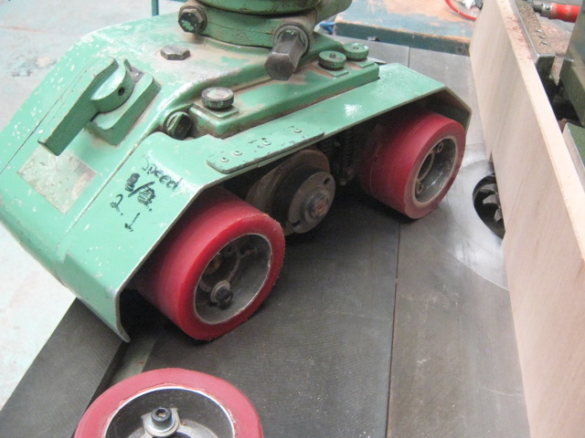
Although when running plywood on the ends over a jointer it can be a little bit rough. Just touching it up on the horizontal sander which is in front of me (photo above) will create a better joint. But make sure to keep things level and just tap it don't push into sander your just wanting to get rid of the rough edgings but still keep the joint straight and square.

Most of the joints looked pretty good. There were a few little hair line gaps but I wasnt too fust. I'm thinking of using Polyurethane glue for this. With this glue it will suck up any moisture that maybe in the joint when will expand and cover up those gaps. You only need a little bit of glue since it expands a lot.

At first was getting a little snip. Adjusted the out feed table since thats where the snipe was occurring. The silver handle with the red lines in it is the adjuster handle that moves the out feed table up and down. turn clockwise moves it up, anti clockwise moves it down.

The old saying you take care of your machines and tools they will take care of you.
Next job was to set up the spindle moulder for making the grove in the plywood parts. What im using here is a two part blade grover. There are 3 allen key screws that will detach them. When tightening them rem not to over tighten doesn't need to be a trazan grip.
Grove cutters like this will have limits as to how big you want to expand the blades to make a wider trench. To make a wider trench you will detach the two blades and place in spacers. These spacers are either plastic or metal rings that have holes in them for the allen key screws to go into. The spacers can range from .1mm to .5mm or more. Allows you to have more play in how wide you want to make a cut. Always best to get a variety of different ones. But have a set of calipers with you so you know what sizes they are.


This cutter needed a internal ring to prevent grover from moving when placed over the shaft which than collets would be placed over them. (has a specific name but have forgotten it) will place in when I ask boss.

After grover was locked in with collets in spindle moulder was adjusting the height. Needed to get the cutter roughly in the middle of the plywood edge. This is rough measurement. There are many different tools to get the right measurement. Like mechanical/ digital calipers that are specifically designed to get tool heights right for routers, spindle moulders, saw heights etc. I don't own these but will be getting them further down the track for this project since ill need them for high accuracy for specific joints. This was not that crucial to get located in the middle. As long as its part partner had its trench located in the same spot the joint would be ok.

You can remove the ring spacers in the moulder plate depending on how wide the cutter is. In This case my whole cutter was sitting above the recessed hole so I used the closest spacer I could find to cover up most of the gaping. You want to do this so you have more surface area to play with.

Moved the metal fences as close as I could get to the blade. You can adjust each fence on its own great for all sorts of different set ups. Wont go on a huge rant for how to set up spindle moulders will talk a lot more in depth later down the track when doing many other jobs on the moulder for other parts of the project.

Always measure your plywood panel parts. Yeah the supplier said it was 15mm but some times the board will variey in this case it was .08mm out which is good. Some times a board can be .2mm out, .3mm out to .5mm out either in the + or -. I rather use mechanical calipers than digital. The mechanics are a lot more precise than the electronics. When using a set of digital calipers do a reading a few times. Also make sure you have taken it back to zero and have reset it. I didn't have my mechanical ones on me since they were back a my other work shop.

We chucked a lot or your old fences out for the spindle moulder since we were doing a big clean up that day so I had to make a new one for this set up. You will find that you tend to need to make a new jig for every different cutter your using or job your doing. I just grabbed a bit of scrap that was going to be the same height and length of the metal fence.


Needed to make a cut out just slightly over the cutter width and the height of the cutter. You don't want too much of a gaping since it takes away surface area for part to run against. If too big of a gap piece will get caught inside and will be messy. Also another main reason for this is to create a safer set up. The less amount of the cutter that is exposed the better.


Need to make the cut out on the band saw. With band saws what ever job your doing always have the neck height lowered as much as possible. Usually the rule of thumb is from the rollers to the work piece a half way point thickness of your finger.
Ill explain further down the track a lot more with band saws since I have a lot more processes that will involve the band saw more.

This is a good notch out. Very safe set up blade is exposed as least as possible and still here is heaps of service area for the part to run up against.

Need to measure the cutter as to how far it will sit out from the fence. I wanted a cut roughly 15mm deep. This didn't have to be exact.
Most of the jobs you do on the spindle moulder you get the measurements as close as you can. Than test it on a test piece than do the final tweaking.
Now with ply due to the alternating grains you dont want to be taking to much off at first so I ran this in two runs. Hitting end grain with a cutter will put a lot of strain on it. You do a job in a couple of passes you will get a better result and prevent things like chip out.

The width of the cut was 6.4mm the top and bottom sections were 4.3mm so 6.4mm+ 4.3mm+4.3mm= 15mm. Pretty good since we last measured the thickness of the board and it was 14.92mm. So I was about .08mm out.
Now this reading will probably change since I was doing this on a test piece without the feed roller. When the feed roller is added it will most likely change the result by about .2mm or more due to the pressure from the rollers onto the piece. Also the depth of cut will change as well due to the pressure of the rollers pushing the piece up against the fence.
I needed to take the middle roller out since if left in it would be hitting the cutter. If the material was thicker I could leave the middle roller in since it would be raised above the cutter.


This is what the roller set up looks like when the rollers are facing the spindle moulder table work plate. You want the rollers sitting 180 deg. Running in parallel with the length of the spindle moulder table plate. As for the fence with the rollers you want a taper that descends to the exit point of the fence from the roller. Setting it up like this will push the piece up against the fence while running under the rollers when being cut. It will provide a constant cut depth across the piece.

But like I said before would need to take out the middle roller. Most jobs you want need to take out the middle roller.


Even though we don't have the middle roller in. The feed roller still needs to be located at this middle point. The blade or what ever spindle bit your using needs to be located in the middle of the mid section of the feed roller. This is so pressure is spread over the part evenly when being run through the moulder.

The height also needs to be set at the right height as well. Since these are pressure rollers they need to be set about 5-10mm or some times more below the jobs thickness. This will create even down ward pressure and help to push the piece through the moulder effectively. I set the roller speed on 1 in the the counter clock wise direction. Im placing my parts in from the right. You can run parts the other way if you have reverse cutters for specific jobs. The rollers can ran the other way but you will find that you wont do this for many jobs. There are a few different set ups for doing it that way which I wont go into.
You will find that you will need to do further tweaking on test pieces before you run the real thing. Meaning you might need to reset the height of move the rollers closer to fence or create more of a taper or decrease roller speed. What I'm doing here is getting a grounding first than seeing what I need to alter to obtain a very good set up.
Before turning on the machine even for tests make sure you go over the whole machine. Make sure everything is locked down fences, roller adjustor's etc. Make sure that your spindle bit is not hitting the fences. To make sure just take the cover plate and give the bit a spin by hand to see whether its hitting it. But make sure and with all set ups the machine is unplugged. When all is good I just turn machine on and quickly turn it off again. This just makes sure everything is k before it hits its top RPM.
Once done with machining use break so you know machine has completely stopped. With most tweaking ill turn off the machine than turn it back on again to do the next test.


Each size piece you will handle differently to the next.

This is just for show, lol. Never do this on spindle moulder lucky its not running always watch your work and use both hands.

This is my camera man. We got bored in the work shop since we only work half days on Fridays. We were the only ones in the work shop. Got to love the selfies.

This is the finished result. The loose tongue will be running in the different grain direction as the plywood top layer. The tongue will be made from plywood as well sanded to just below the width of the trench.

The rest of parts are placed on a pallet on the back of the ute and will be taken back to my other work shop for the next stage.

Used a blanket than ran belt straps over it to secure it to tray. Blanket was used to protect edges from straps. Ute tarp than ran over this.

This is just a close up of the plywood layers. What im doing now is using some of the scrap offcuts of the plywood I had from cutting the parts out of the sheet material. What I need to do is sand these down to 6.3mm which is just below the width of the trenching.
I can not put these through the thicknesser due to the alternating grain laminates. only put timber running in the right direction to the blades.
So I need to be patient here. What I do to one side I need to do to the other. I need to take .5mm off in each go. Should never take off more than this since it puts too much strain on the belts and can burn them especially with larger pieces. A drum sander is not a thicknesser. Plus it puts strain on the tracking belt and pressure rollers as well also the plantons.

placing the first parts of plywood scrap through the sander. These scraps started off at 9mm so I needed to start sanding at 8.5mm. Try not too sand parts by them selves that are shorter than 300mm in length can get caught in the sander or caught between gaping at the back of outfeed table to back pressure roller. I usually use a sanding tray for parts that size or smaller. Like a thicknesser sand edges first than faces due to surface area.

The push stick we normally use at work was too thick so I had to use a 3mm piece of MDF as a push stick.
Always use a push stick with the bigger drum sanders. Small drum sanders like the one I have at home are operated in a different way. This prevents the piece from being stuck in side this is usually caused from there is not enough friction on the tracking belt. Another reason is that the belts are getting to clogged up and need to be cleaned or replaced another factor is the tracking speed is too high or your taking off too much.

This is a digital drum sander quite useful when wanting to get some precise.
The sander runs on 3 drums. first drum we use for 60 grit the middle we use for 100 grit and the third we use for 150 grit. Now you can really place what ever grits you want in the drum sander as long as its increasing in height towards the finish drum. Now we do use 180 grit belts but I would not recommend using anything with a higher grit than this. 180 grit is probably too much usually 150 use just all you need. These belts cost a lot so its best to get as much out of them as you can.
Drum sander are really to get the bulk of waste off parts, to machine parts to specific thicknesses or to sand timber that has grain running in all sorts of directions.
When doing large jobs sand the bulk of the dry glue off. Before doing the final finishing turn off machine and clean out the machine. Usually stones ( which is a term used for dry bits of glue) get caught in between the rollers and belts which can cause the belt to burn or cause the belt to make a dint in the timber.
Make sure drums are running parallel to the tacking belt and also make sure that they are are the right pressure and hight levels. The drums will be backed off from one another in height. The 60 gritt doing the bulk of the work towards to the 150 grit doing the fine finishing. Now after this hand sanding still applies usually work from 180 gritt to 240 gritt to 320 gritt to the 400 grits etc. Depends on the finish you want to acquire.
When turning on the machine turn on belt one first let it power up first to hit high performance level than hit second than do the same like the first than hit the third one than hit tracking belt.
When doing finer size adjustments you can use the turning wheel at the bottom that does small adjustments instead of turning off the machine and resetting it. To reset the machine digitally you can do miner adjustments on the control panel but major adjustments the rollers and tracking belt must be turned off to do so.
Like with many machines to is too much to explain. I wont be going on too much about the sander just some basic things like above. Again there a great books, dvds and youtube videos that explain this machine in a lot more depth. But its one of those machines that you need to be taught in person. There really is a lot to remember with this machine there really is no quick run down can usually take 30 mins to explain or more to explain it properly.

Brand type. This is a very old version I think its about 20-30 years old. Age should not turn it away from purchasing machines usually the older ones are better than the newer ones.

This was the finished thickness of the spline strips. Now I measured them and noticed that they measured at 6.3mm not this means that the sander was out by .4mm not you may think thats not too much but with this machine and industry that is. A few things could not be calibrated properly or where I was putting it in machine the drums may have been knocked out of alignment slightly. I knew my calipers were reading properly since they were my mechanic ones from my own workshop.

Mechanical calipers using them to measure thickness of spline connectors. You want a tight fit but not too tight. Always keep testing spline in trench to obtain a good fit.

Rest of the splines sanded. The other scrap parts were 12mm and 15mm so I really did need to be patient.


Had to make the shallow convex clamp sticks for clamping down the middle joint section of the plywood panels that were getting fixed. There were two lengths of 600mm and 2 lengths of 400mm. I have the clamps to do all of them in one go as well as not having the time for waiting in for each one to dry than change over for the next one.
What I was going here was creating a curving on each side by not machining in the middle. You only need to do this a little bit about 2 passes on each side. Before doing this runner over jointer in one go and obtain a true flat/ square edge. I decided on choosing 32mm compared to 22mm due to its clamping service area plus being a lot more structural stable and also being easier to clamp a clamp to it.
I marker a line half way down the pieces than half again on each side. This second half mark is around about where i want to finish the jointing cut.


Next for all four pieces needed to just sand down to form more of a gentle curve on the horizontal sander using the open side section which makes obtaining curves a lot easier. Normally I would use a bobbing sander but at work we don't have one of those. With this you don't want to take off too much only a small curve is being produced here. The aim is to just get out the machine marks left by the multiple rotations of the jointer blades. So you want to go reasonably fast not staying in one area for too long and applying the right amount of pressure. Your just wanting to place a small amount of pressure but like all machines your just guiding it let the machine do the work.


Use a straight edge and run it across the middle of the piece where the curve is being produced. This will show a gaping on either end and produce a rock from the straight edge on the piece when moved from side to side. You can also use a flat bed like a jointer in feed or out feed table or a panel saw or rip saw top plate. The arrows so the mid point and the secondary mid points.

Double checking the measurements of the trenching. The trenching measured 13.7mm after using the mechanical calipers. So times this by 2 which is 27.4mm and this will be the trench width between the two pieces. The splines need to be around 25mm you want enough room for glue and also if there is movement later on.

reading of mechanical calipers. The side section shows the main mm unit. Where the dial gauge is showing to a more precise measurement of 2 decimal places.

These were the cut up ply pieces I was going to need for clamping. The smaller width ones being used as clamp blocks, the other pieces being used as stickets to raise the boards off the sache clamps. As well some were being used as the clamping plates that sit on the plastic that covers the joint which also sits under the small convex curved clamping beams.

Just doing a final check with the joint splines to the boards. They all fit very well. One of the boards has a small lip which wont be that bad since its in an area where it will be removed due to being in an offcut section. Most it also should pull in when being clamped


Finished result. Need to have enough gaping for glue also a little bit extra room for expansion if there is any which is most unlikely there will be.
All the pieces for this have been taken to my workshop and will be clamped up at my work shop at a later time.


When doing gluing up jobs its always important to get your station totally ready before any gluing takes place. This will prevent you from running around like a headless chook trying to find stuff while glue is beginning its curing stage. Each glue will have a different work time so its important to be totally ready for the job having everything at arms length.
Place everything on your table or if you have one on your tool trolley. This will be things like a straight edge, clamps both sache and G clamps (Again depends on what your gluing up). Squares, rag with damp water. (in this case do not use water on polyuerthane. This is because one of this glues functions is to remove moisture from the joint. You wiping glue off with a very damp rag will defeat the purpose to some extent. Although the glue does need a little bit of moisture to cure so you need wipe the glue joints with a very damp cloth 1 minute before handling). Tape measure, spirit levels, other kinds of rulers, tape, clamps blocks, support stick strips.( avoids sache clamps sticking to material). Also a mallet or small hammer and a hammer block. (cork block) This is top tap boards that maybe springing up when being clamped.
You may need other specific things but again depends on what glue job your doing.

Now also before any gluing up takes place always do a dry run. All a dry run is is clamping up the job as you would do without any glue. This will show you whether things are going to go together properly whether things are going to be square, have no bow or twist etc. Falls under the same principal cut 1 measure twice.
Make sure arrows face down for the clamping beam. The arrows indicate which edge has the shallow convex curve.

One of the things I needed to do before glue up was cutting plastic strips for the joint sections so the pressure plate strips would not stick to the material when the glue raised itself up through the joint. I prob would not use this again. Baking paper. ( Glad the good quality one) works well due to its oily texture will repel most glues.

I decided on using Polyurethane due to its ability to suck moisture from the joint. Its ability to expand when it cures so it covers up gaps. Also is very easy to clean up when dry. Solvent/ chemical resistant so most stains/ oils and other substances wont effect the glue area. Also its solvent free so it makes it easier to clean up on the material (wont stain the material heaps)
Now you only need to add a small amount compared to other glues as this glue expands. You have about 10 mins of work time with this glue but this also depends on the temperature. As for clamping time you have about 4 hours. Again this depends on temperature. For me I like to live things in clamps for 24 hours. This is because after 24 hours the maximum bond strength has rich but this depends on the humidity and porosity of the materials being bonded.

For dry run and when glue up takes place you want to see whether there is any gaping caused from twisting your bowing. you will see this if you have a rock with your straight edge and also there will be a gap under the straight edge. This will show you that its not level as well. The good thing about this straight edge is that it has a machined edge and also has two different spirit levels in it.


Use the straight edge/ spirit level at different areas of the clamp job to get an average as to how level it is and how well its clamping up. Now you may find too much clamping pressure can make the jointed pieces want to spring up. You dont need that much pressure when clamping up. No need for Tarzan grip.

Place plastic over the joint when glue is applied and stick it down with masking tap so it doesnt move and stays on the jointed section.


Another tool to use for this is a angle gauge. During dry run and glue up I used the angle gauge at each corner and middle. The readings were around these majors. Was quite happy with this.

When applying the glue again you don't need that much. I used a padel pop stick to swear the glue across the spline to get an even amount of glue layer. Remember to wipe the glue joints with a very damp rag 1 minute before applying glue since glue needs a bit of moisture to cure.

There are a few things to check when clamping up. Check these both in dry run and during actual glue up. Check that the glue joint at the ends has come together well. There is a bit of a gaping between the splin and the back edge of the grove. This is ok since this will be covered when the glue expands.


Also check down the side to see whether its running straight/ straightish. Mainly at the joint section.

This is what I was talking about with the ruler.

Give a few minutes and you will start to see the glue expanding.

Remove the plastic that is covering the joint at the end so air can get to it so it can cure properly. You want a bit of over hang with plastic so when the glue expands out it doesnt go all over your clamps.

Another thing to remember is to look down the side this will also show you whether there is a twist or spring up. Try looking at from about a meter away.

This is after about 10-15 mins you can already see the glue expanding out. As you can see you dont need that much glue.


Finished glue up/ clamp job for the drawer box lid.

Finished clamp job for drawer box lid and Ikebana shelf. Now to leave for 24 hours. I was going to clamp up for but found out that my other clamps they were all different widths. When you obtain clamps try and get clamps that are roughly around the right size in width. This is make things a lot more balanced when clamping up. Will have to do the other two the next day. Plus I don't have much space in my work shop.
If it wasn't for me not having much room to play with the thickness. I would not have a clamping plate over the joint. I would have the middle sache clamps running over the top. This would spread out clamping pressure plus counteract the spring up from the other jointed boards.

This was the next day after I took the first lot out of the clamps. Glued very well and feels very strong.

For both the large piece and the small piece I place on my multi combination bench since this is a very flat service. There is like no rock with the board. Shows that it clamped up well and did not cause any major bowing or twisting.
The glue will be easy to remove and will be removed with cabinet scrapers and sand paper before veneer is laid.

Ready for the next glue up for the other parts.

Just clamped up the next lot of boards. Worked pretty well like the other ones. The only thing is one of the sides of the joint created a bit of a lip on the drawer box lid. This wont matter so much since after light sanding if its not gone will make sure its on the major off cut side.
.JPG)
I started off sanding at 15mm. The panels were ranging around 14.7mm- 14.9mm. Panels really are not their true size as advertised. I sanded at .2mm increments doing the same to each side. I ended up finishing at 14.1mm. So once veneer would be added .6mm to each side the panels would finish at 15.3mm. So I was .7mm out, which is ok as I still fall under the +/ - 1mm.
This wont be such a huge problem for the Ikebana base and top drawer base. But if not machined properly this could be a problem for the drawer box lids. I have stated that I would like to make the rebate for the lids to sit on in the drawer boxes to be 16mm. I'm beginning to think that maybe making it 17mm or 18mm. This is so that if the lid does move it won't protrude over the actual drawer box making it stand out in a bad way. But further discussion will take place when coming up to that stage.

Was placing one at a time through the sander and using a push stick, I could not afford to get ripples on them.

Some of the panels didn't clean up completely but I wasn't too fust since they were in waste sections which would be cut off when being cut on band saw to make shape of part.

Blew through a section of one of the layers. This is because there is a slight bow in the sheet. Had noticed it when looking at the side of the panel and noticing that some sections of the outer layers varied a little bit in thickness. I'm not too fust about this sections since it is in a waste section that will be cut off.

Had to use the jointer to dress one long edge on the panels so I could use it as a reference to sit on the panel saw docking fence. I moved the jointer fence closer to the front to dress the plywood on the sharpest part of the blades. Again wasn't wanting to take off to much to avoid chipping but also to have maximum off cut to play with.


Just had to cut the panel to oversize size before transferring the part shape to it. I took most of the off cut off the larger section since when coming to finished size I didn't want a small section where the small part was connected to. This would create a structural weakness within the part.

When cutting boards you dont want the blade to high. You want the blade just sitting above the job height. This puts less load on the blade, exposes less blade creating extra safety plus limits breakout. I still had to have the scoring blade on since I was cutting through cross grain layers.
No comments:
Post a Comment