I have placed this pictures in some of the other posts but I will talk about this more here in more depth.

I have been thinking or altering the next taper and making it less of a taper but will think about this more when coming closer to the point where I have to shape them.
This next taper will not happen till all the joints are finalized.

I have decided on cutting out some of the cabinet buttons as they are not needed. I wont need cabinet buttons to attach the moldings to the base since I have chosen a different construction method so these can be taken out for sure.
Also some of the other cabinet buttons have been taken out to make some room for the curved corner blocks I'm thinking off adding. The cabinet is going to be quite heavy and there is going to be some extra support added to the rail and leg connections to support the weight.
I don't really want to have screws attaching them to the structure. Earlier I mentioned that I did not want to use screws hardly at all. What I will be doing is using dowels to attach them to the framing but having them exposed to create a still cool detail but also to reinforce the structure. I will really only be doing this if I have time.

The maple feet that will be going on the bottoms of the legs will only be made when the tapering is finalized.

A while ago I mentioned that I may need to add bottom central rails if the weight is too great. I will only be making them if I need them. I don't think I'll need them but there is still the possibility that I may need them. I will only see if I need them when I do a massive dry run with all the cabinet weight on it.

Probably out of the whole project this is the hardest part of the construction. Well its actually quite easy is more about the error factors that can happen very easily even when being really careful and precise.
The angles with this project are very crucial. If out by half a deg and on a span of about 250mm from one point to another can set off an error of 3-4mm.
I have already cut the angles on my rails there seems to be some error points I will only consider cutting them when I have made all the mortises and have done a dry run to see how well everything goes together.
If they are out I will cut them again I'm thinking of getting a festool drop saw that will give me top accuracy. The cuts I made with these rails was on my old table saw that I had to do a lot of tweaking when making the cuts.
What I will do is make the cuts on mock up scrap on the drop saw and see if everything goes well if it does I will cut down the rails by about a couple of mm to obtain better miters.

When all the mosrtises are sorted out and everything goes together well I will be making two 8 mm dowel holes on each side where the floating tenons will be going through. The holes will be further drilled in when assembly has taken place. Once that is done dowel rods will go into the legs. The dowels will slightly over hang and will be cut off with my flexi Japanese hand saw. This dowels will act as locking pins creating extra strength plus also they will create a decorative feature in the contrast to the blond timber to the dark timber of the wenge.


I have a master craftsman who works at my work and this was a slanted mortise jig that he made for one of the tables he was building. This one is only set for one angle cut the principal is quite the same for the one I'm making its just that its adjustable.
I got some great pointers from him with making my own and what to watch out for.
Pointers:
- Making the jigs axis line up with the axis of the mortise cutter. ( axis of the actual length of the mortise your making).
- Toggle clamps to prevent movement but also a secondary clamp to provide extra support to prevent the leg from swaying.
- Slow down the infeed machine speed this will limit micro movement. The mirco wobble is mainly caused with long cutters when the cutter is finished the cut and than is coming out. the mirco wobble can make a joint .1-.3mm wider.
- Make jig left and right capability, this will half down machine set up.
- Add adjuster screws so you can make leg sit parallel to jig and mortise alignment.


With my jig to prevent further movement I decided to place some sand paper down on the base where the legs will be sitting on. This will act as a friction pad which will help to prevent the leg from further moving.

The middle rail may need to be slightly cut down because of the errors with the front and side rail angles. This will only need to be cut down slightly like about 1-2mm.


Laminated up some scrap ash to be used as test mortise pieces for when machining the angled mortises into the legs.


Roughly seeing what the parameters for the mortiser were so I could see whether I was able to achieve the morties I wanted in my legs.

I made a quick sketch up drawing of the angled mortise jig.

The bottom plate of the jig would be clamped to the work plate of the mortiser.

Made the jig so it could be used to machine the left and right mortises on each leg. Doing this meant that I did not need to make separate jigs for left and right. This would also half machine set up time.

Tenon set up measurements for back legs in accordance to jig. This would show me what measurements I would need to refer to when making the angled mortise for the back of the legs.

Tenon set ups for front legs in accordance to jig.

Tenon set up for side legs in accordance to jig.
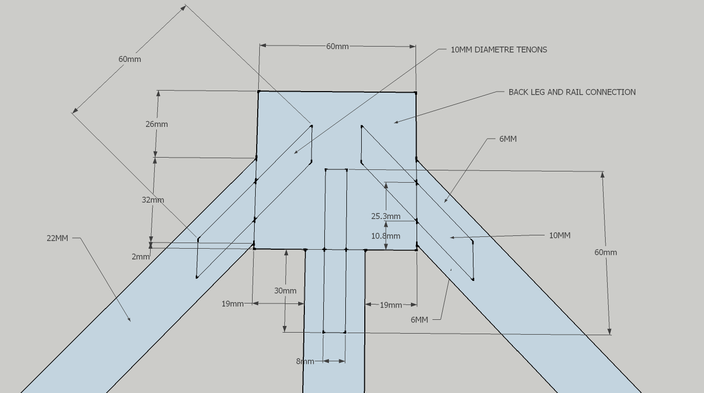
Further detailed measurements for rail and leg connection at back.

Further detailed measurements for rail and leg connection at front.

Further detailed measurements for rail and leg connection at sides.

Over all angles for leg and rail connections

External and internal miter lengths for rails

Glued some timber up to make test pieces to run test mortises before running them on the real thing. These angled mortises had to be highly accurate.

Building the angled mortise jig. Piano hinge acts as the folding mechanism with the bottom plate and work plate of the jig.

Angeling the brackets for the jig on the panel saw using the miter attachment.

To create better support with the angled brackets I made a connection base plate. On the base plate would be two brackets. What I'm doing here is making the connection dowel holes to connect the brackets to the base plate.
The brackets are connected to the base plate with dowels.
The base plate would be clamped to the bottom jig plate.


Visually seeing what the new shape modifications could look like to the front and side rails. They had to be changed due to the mortises sections.

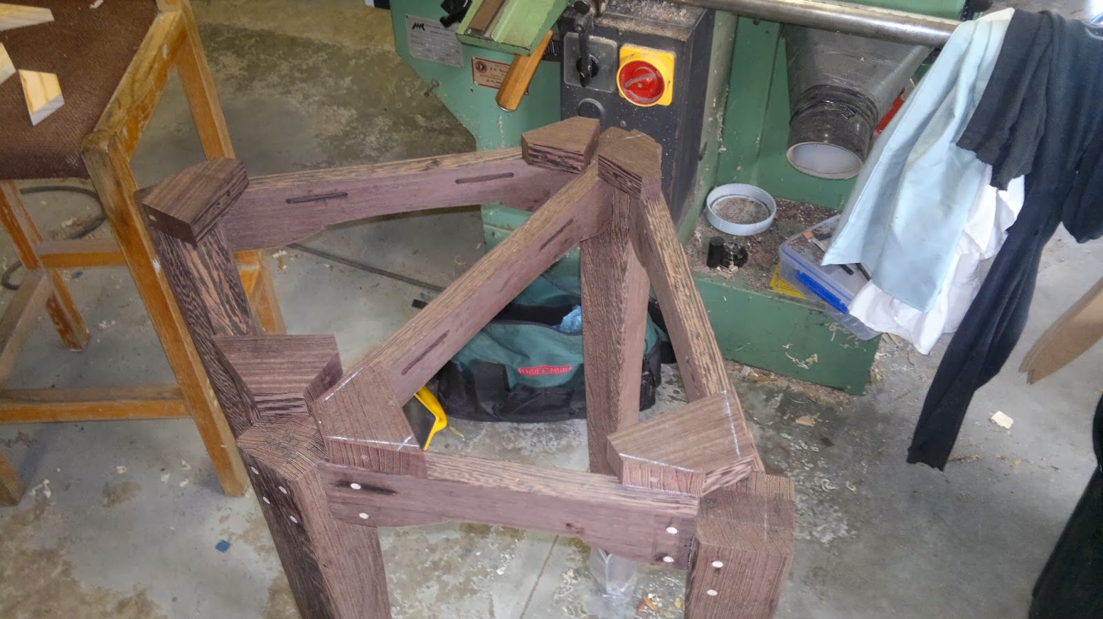
Seeing what the legs look like on the base so far visually. Just double checking that every thing fits


Test blocks in connection to mitered rails.

Band sawing maple timber to make cabinet buttons to connect bottom section to top section.


Obtaining the corner block shapes for the front leg section.

Obtaining the corner block shapes for the side leg sections.

Obtaining the corner block shapes for the back section.

I did a dry run of the cabinet legs with the rails so I was able to get a drawing layout of the cabinet buttons. These cabinet buttons will not be cut out until the whole bottom section is assembled. All I wanted to do was get the shapes of the corner blocks and place drawer them on the wenge stock. I wanted to drill the angled dowel holes in them first before cutting them out. The lock dowel pin holes would be 6mm in diameter.
These dowel pin holes would follow the same processing as the ones on the legs and rails.
The shapes were just drawn onto tracing paper.

Making the cabinet button rebates on the panel saw. Used a board to prevent the off cut from falling down in the saw cavity. Also it gave more support due to increased surface area.

Drilling the screw hole clearance holes for the cabinet buttons on the drill press.

Getting ready to cut cabinet buttons to finished lengths.
The kapex 120 festool compound drop saw will be used to recut the rail mitered joints to get a very accurate miter. The angle guage I was originally using was not very accurate ( found out it was out by .5 deg).
I ended up buying a new bevel square and a angle gauge that works hand in hand with this. I will use these to measure the test pieces to make sure I'm cutting the right angles before cutting it on the real thing. Also I will get a finer cut on this saw with the finer toothed blade I have compared to my table saw blade.

Decided to make new floating tenons as the other ones were a little bit too loose. The loose ones I will still be using when doing the dry runs and doing the tweaking with the clamps etc.

Since the floating tenon material was quite thin ( 10mm) I had to use the fence instead of the bearing on the router bit. I could use the bearing but it will leave a shallow profile. A two high profile would mean that I could not flip it over and obtain the same profile on the other side since there would be no material for the bearing to run on.
To get the same effective profile on the other side the starting profile needs to finish just before the middle point of the thickness of the material.

The digital thicknesser was out by about .1mm
The mortises I made were ranging around the 10.1-10.2mm mark. Even though the cutters were 10mm it has bumped out due to the mirco bevel. I decided on machining the floating tenons to 9.9mm in thickness. You want a tight but not to tight fit.

Also made grooves into the floating tenons basically making a really large domino. What this does it allows the glue to travel up the channels increasing the gluing surface area.

A while ago I spoke about needing to cut down the rails a bit since the angle gauge I bought was out by .5 deg.

I machined some scrap up to the same width as the widest point to the final rails I was planning on using. The only thing is that these test pieces are cut 2mm shorter than the original drawings. 1mm would be taken off each side to the final ones to match the finished miter lengths as these ones.
I wanted to test these first to see if everything was going to go together properly before re cutting the real rails.
I was quite happy with how the test pieces went it all fitted together properly without really any issues.


Making sure that sections of the legs were even before doing the real thing. Really it was more just being curious as to how level the structure was. This would show me to some extent as to whether some of the legs were longer than one another.

Re doing the miter joints for the front rails. I used blue painters tape to limit the breakout from the saw since wenge tends to break out heaps. It would be breaking more out the back where the blade is finishing the cut compared to the front.
I checked each angled cut on some scrap first using my new bevel square and new angle gauge adjuster which corresponds to the bevel square.
My drop saw has been knocked out of calibration by about .5 deg so I have to make sure I'm cutting the right angle so thats why tests are done first.

Cutting the side rails. Like the front rail cutting 1mm off each end.

Doing a dry run to get all the kinks out with how to clamp the whole thing together. I used clamp blocks to help provide clamp pressure at each miter joint. The belt clamp would be pressing down on the timber blocks when being tightened up.
The clamp blocks are 20mm in thickness and there are 2 in each stack. You want to place them about 25 mm away from the miter joint so you can still see whether it closes up the joint but also the closer you are to the miter joint the more pressure will be placed on it.
The important thing is that you don't want to place to much pressure on the rails where it will comprise its position. The belt clamp doesn't need to be super tight, just tight enough to close up the miter gaps.
The only thing is that where the hooks connect to one another is the weakest clamp section. I wanted to try and keep this on one of the leg sections. Although it can't go over the front or back like like in this picture. This is because a sach clamp has to go there to provide pressure to clamp up the middle rail.

Rags are placed between the legs are belt so it doesn't damage the face of the legs.

The main slack points in the belt is the middle point of the belt where it meets to th mid point of the rail. This is also why you want to keep your blocks closer to the miter joint.

Further away view of dry run.

These maple feet will be glued on after the main glue up is done but will need to be sanded up first.

At the front leg and back leg I'm going to need to place in a clamp block where the belt will sit over it. This clamp block will provide pressure from the sach clamp and will also prevent the sach clamp from damaging the face of the legs.

I wanted to check how level the job was. The most level thing in my work shop is the top of my multi combination machine.

I found that the middle rail had to be cut down just a little bit more. This is because its current length was pushing open the inside miter joints of the front rails at the side leg sections. You don't want to force the middle rail in it should just sit in quite easily with out any force or any slack.


Even though they are small gaps need to get them smaller to provide a better glue joint. They came down when I cut the middle rail to the correct shoulder length.

I decided on doing a weight test to see if the rails and legs could take the rest of the cabinet. I was concerned a bit whether I was going to need a bottom rail section. This is pretty much all the weight that will be going onto the cabinet besides some of the other small edges and items that would be sitting in the drawer boxes and on the shelves of the cabinet. It actually held up quite well.
In this test there is no glue, no middle rail, no locking dowel pins and now clamp blocks. The fact that it held up quite well without these shows that I'll have not problems where the extra support sections are added.


Since I was happy with the whole dry run I had to sand all the parts up before assembling. I started at 120 grit than worked up to 180 than 240. I was basically using what sand paper I had in my workshop. Before sanding all the codings off I labeled each leg and what the side codings were. This would make things easier when coming to assembly.

Hand sanded all the parts and repaied any chipped out sections with ebony putty filler and super glue.

Placed sanded parts on rails to keep safe.

The back leg needed to be planed down a bit to fix up a damaged section. This was the section that was damaged from the bearing of the 45 deg bevel cutter from the router. Most of it I was able to plane out the rest I repaired with super glue and ebony bog.

Used super glue and bog to fix up chipped out sections in the rails. Most of these chip out sections were on the side side section of the rails.

Used the rasp to finish off the last of the 45 deg bevel edging on the edges of the rails. These were the sections where I could not use the router since there was no surface area to run the router bearing on. Normally you would route the pieces before making the miters.

The front and back leg are a little bit out of alignment with one another not much to really notice unless you take a ruler to it.


After sanding everything I did another dry run but with the extra clamp blocks at the front and back legs. I ran a sach clamp between them and provided clamp pressure.

Cutting the middle rail to size, masked off edges to prevent grain blow out.

I plan on using epoxy for the glue up since its easier to keep clean, its stronger than the other glues I have been using but its open work time is a lot larger compared to the other glues I have in my work shop like the polyurethane or tight bond 3 etc. The epoxy is hard to clean up when it is totally dry so I decided to mask off the areas around the joint sections with painters tape. Any excess glue will go onto the tape.

The epoxy is the same type I used for when gluing in the magnets into the doors.

The acetone will be used to remove any un cured epoxy from the timber surfaces of the parts.

The epoxy is 2 parts resin and harder. Add even amounts mix than sit for 10 mins. After this mix again than apply. I needed to make enough to cover all joints I did not really want to make another batch half way through the glue up despite the fact it had a 2 hour work time window.
I did the glue up on a cool day so I did not need to rush.

The job is clamped up first upside down, this makes things a lot easier with the placement of clamp blocks etc. The belt strap needs to be placed about the half way mark of the width of the rails to provide even clamp pressure all round.
For the glue up I used the new floating tenons I made.
Before gluing up I had to make sure that the rails had enough movement where they could be made flush with the tops of the legs. Some of the floating tenons I had to make shorter in width to achieve this.
I placed glue in the mortise of the rails first than placed in the floating tenons than placed glue into the mortises. I also placed glue on the end grain sections of the rails but not too much where it would cause too much excess glue run out.

Once the belt is on tight I flip the whole job over and than place the sach clamp down on the top and clamp the middle rail to the legs.


Front view

Front side view

Side view.


The job will be left clamped up for over 24 hours to get an effect bond before taking it out of the clamps.
I went around the whole job and cleaned off any uncured epoxy resin with the acetone on a rag. This will just make things easier later down in the cleaning process.
After all the clamps were placed on I made sure that the rails were flush with the tops of the legs. I just knocked some of them with a rubber mallet to get to the right position. Also checked all the measurements making sure things were square and in align. Some sections were a little bit out but I couldn't do much about it.


Cleaned off the painters tape after leaving the job to dry in the clamps for about a day. With epoxy it usually needs about 6-8 hours to dry depending on the temperature. Although it gains it maximum strength usual after 2-3 days.

Began to sand the maple feet that would be attached to the legs.

Mixed up a batch of epoxy to attach the dowels into the feet than attach to the legs of the cabinet. I let the epoxy sit for about 10 minutes.


Attached the maple feet to the legs with painters tape. I had to make sure that the end grain of the feet was in the same grain direction as the legs.

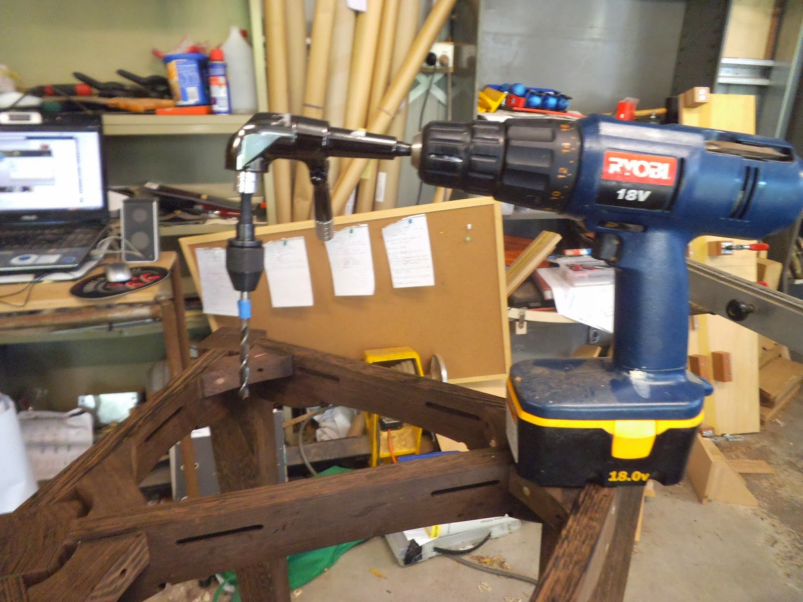
Drilling further into the lock pin holes. I needed these holes to go further into the floating tenon for the lock pin dowel to go into and be glued in. These lock pins would create extra strength and also provide a decorative element to the cabinet.

To know how far I needed to drill the holes I masked off the stop point with painters tape.

I sat the cabinet up so the weight of the cabinet would be acting as a clamp as well.


Another visual dry run of the base on the glued up framing.

I cut up heaps of locking dowel pins and over sized them by 5mm. I glued them into the holes using quick setting loctite epoxy. I needed a premixed one with a small nozzle head so I could get it into the 6mm holes.

Tapped the dowels in and left to dry for about 4 hours.


I made the dowels flush with the legs and rails by using the flexi japanese hand saw.
Making the curved corner blocks.

I wanted to make locking dowel pins into the corner blocks. I did want to use screws as they look messy.

I needed to set the table on the drill press to 30 deg. I was surprised how accurate the drill press was.

The set up required a clamped down fence so I could locate the drill bit into the middle of the stock piece every time.

I also needed to clamp the piece to the reference fence so the piece would not move when drilling. I placed the drill on high speed to get a better machined effect.

I was drilling 6mm diameter holes for the curved corner blocks, same as the rails and legs. I decided to drill all the holes before cutting out the corner blocks since it would be a lot easier.

I had to change from left to right in the set ups as there were left and right holes going at 30 deg.


I did test cuts on scrap to make sure I got the right angles for the corner blocks before cutting it on the real thing.

Half way through cutting the angles for the corner blocks.
Cut all the angles for the corner blocks now they just have to have the shape transfered onto them and cut out on the band saw.

Front corner blocks.

Side corner blocks

Back corner blocks.

Band sawing out the corner blocks just cutting on the drawn line.

Using the bobbing sander to sand the curved edges of the corner blocks to remove the band saw marks. The edges will have a slight bevel on them before gluing them to the main structure.


I got these two attachments for my drill that have helped me out heaps in getting into the tight areas to continue the drilling so I can knock in the locking pins. The spaces were too tight so I had to use a horizontal drill attachment to allow me to get into the awkward areas. I also had to by another attachment since the 6mm forstner drill bit did not have a hex attachment.

Glued in the last of the dowel locking pins for the corner blocks. I used polyurethane glue since it was more easier to get the glue into the holes compared to the epoxy. Now I just needed to wait for them to dry before cutting off the over hang sections
No comments:
Post a Comment