
Funds are getting a bit tight and need to make a veneer router jig do clean the seam lines for the figured maple.
I specified in an earlier post that a using a router to clean the seam lines of the veneers would be a lot better than using the jointer since the RPM is higher which would give a smoother cut. Also you would avoid having the veneers being out of square.
I'm planning on making a router jig to clean the seam lines of the veneer from the left over plywood I had in my work shop from the substrate parts and also other jig parts. Plywood will be the best alternative since it wont shift as much compared solid timber. Also I hate using MDF and would rather use plywood since its better to glue and better to drill and screw into.
The jig will be the same as the one I saw in my veneer book but with a few alterations. It wont be as long due to the plywood offcuts I have are not long enough. The original design was about 1200mm in length my jig will be around the 1000mm mark. This is k since my longest veneer part is around the 870mm mark.
.JPG)
I had cut some of the plywood scrap into parts for lamination. I was laminating the top and the bottom pressure pads that will sandwich the veneer when having the seam lines machined with the router.
.JPG)
Used a piece of plywood scrap and made slits in it than spread out the glue out. Before I did this I sanded and scored the glue faces to create a better bond surface.
.JPG)
Clamped up the laminated pieces. I decided to use a caul in the middle with baking paper. I needed to clamp up both laminates at the same time since there are not enough clamps in the work shop at tafe to do two big clamp jobs like this.
Before clamping up I found leaving the job for about 15 minutes first worked best since It gave the glue enough time to bond preventing slipping when clamping up.
I used the same principal with the clamps like with the other clamp jobs ensuring that the clamp pressure diameter fields crossed over into one another. If there were small gaps at the edges I was not that fust since the edges would be covered with quarter sawn vic ash. I needed to use quarter sawn ash since it would not move as much compared to back sawn plus it is very hard and wont get damaged very easily.
I'm not too fust with the faces being damaged from the clamps since Ill be placing the laminated plywood pieces through the wide belt sander at work.

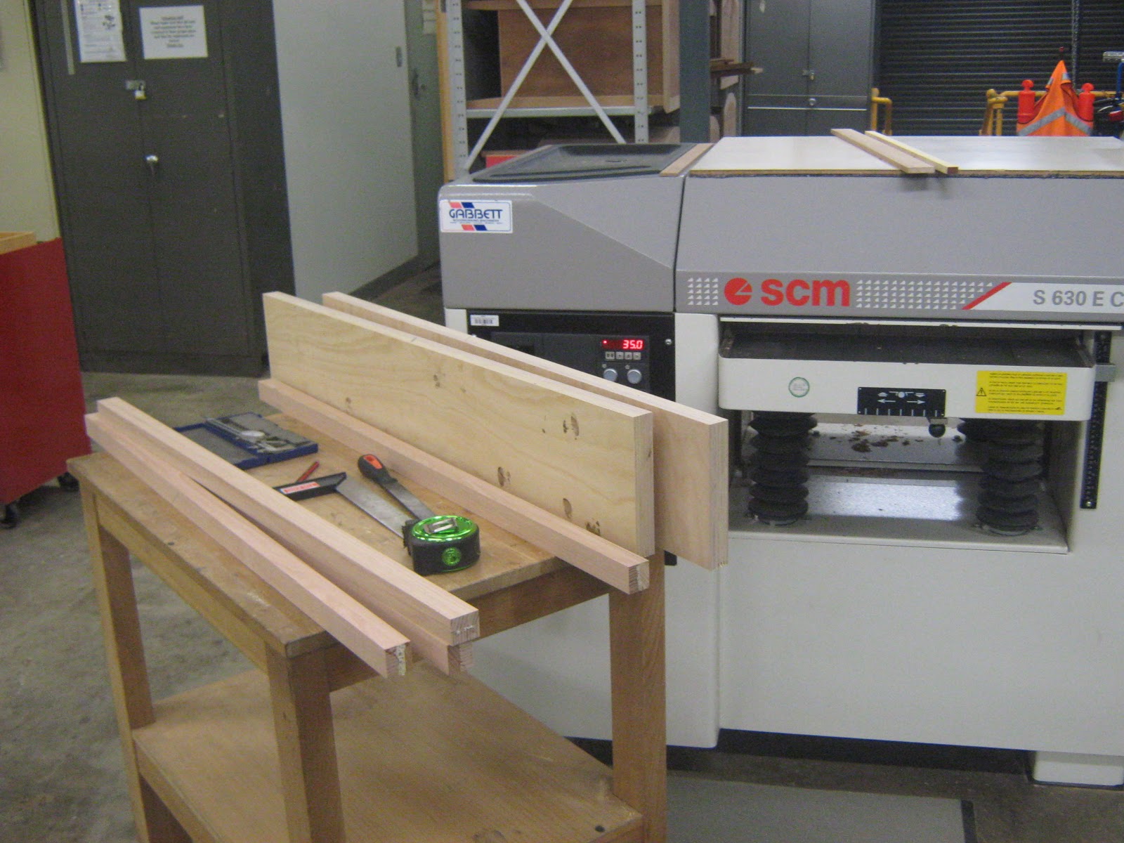
Began ripping, docking and thicknessing parts getting them ready to be laminated. These parts will be the edgings for the top and bottom press sections that get connected to the previously laminated plywood. Also some of the timber will be used for the bottom support bar and the top clamp beam.
Most of this timber I had just lying around from old projects in my work shop.

Parts ripped and docked over size. All that needs to be down before gluing them up is sanding down the glue faces and scoring them. Most of these parts will be pressed up in the sach clamps and F- clamps.

Every time you do a lamination job its best to mark the edges with a triangle. This will show you what the glue faces are and how they should be stacked when being glued up and pressed.

The glue faces needed to be sanded so I needed to sand them through my drum sander. Now each pass that is taken you should only be taking off about .3-.4mm. The motor both for the drum and tracking belt is not as strong as the wide belt sander I have at work so more care needs to be taken when sanding through this.

When using this open ended drum sander you should place the parts through it and hold each piece in a very similar way to the jointer. Making sure controlled pressure is applied at the in feed section and out feed section. You want to make sure you don't get snipe or ripples. If your getting ripples its most likely your taking off too much, the belt is not going the right speed, there is too much slack in the belt or the sander paper is too clogged and needs cleaning or replacing.
If your getting snipe your in feed and out feed tables may not be sitting co plane or they are not at even heights. Also you may not be applying right pressure on in feed or out feed section.


After the sanding was done the glue faces needed to be scored and after that lightly sanded with some 240 grit sand paper.


Parts are now ready to have their glue faces sprayed with water and polyurethane applied to them.

Pressed up the end pressure rails in the sach clamps and F-clamps. These will be connected to the ends of the plywood base and top base.

Applied glue to glue faces for top pressure beam and now is ready to be pressed up with clamps.

Pressed up with clamps and now both clamp jobs need to be left for 4 hours to dry.

Started to run out of the polyurethane and needed to keep that for the veneering. What I'm using here is tight bond 3.
This lamination job is the bottom support rail.

Job clamped up and now needs to be left for about 3-4 hours.

Before running the laminated plywood sections over the jointer to get one edge totally sqaure I needed to remove most of the dry glue. Dry glue can tend to blunt the blades so its best to remove most of it before running over the jointer.
To remove most of the dry glue I find just using a file works quite well.

Also needed to clean off the dried polyurethane glue from the edges of the timber edging that will be glued to the top and bottom pressure pads for the jig before running over the jointer. Same reasons as above will blunt the blades a lot more.

I needed to get one edge square. I picked the edge that was going to require the least amount of passes over the jointer. I stated this in one of my earlier posts but its best to use the far edge of the blades on the jointer. This is because they are sharp and don't get used that much compared to other sections of the jointer. Plus running plywood over the jointer will blunt the blades a lot more due to end grain and long grain on the edges.

Once I got a clean edge to reference from I was able to rip the other side on the panel saw. Once I had two clean edges I was able to cut off the ends.
After cutting on the panel saw took the plywood sections back to the jointer and ran the edge that I just cut on the panel saw back over the jointer. This is so I would get a better glue joint for when I connect the timber edgings to it.
After running the timber edgings over the jointer. I needed to run them through the thicknesser mirroring the other edge and face. I wanted to get the edgings as close as I could to the same thickness as the plywood panels. I decided on using my calipers and measured the plywood sections. I wasn't too fust that much If I was going to get a slight step since I would be running these sections through my drum sander at my work shop.

After parts were machined sqaure needed to mark out the sections where the biscuits were going. Each biscuit's centre point is 50mm away from the other. I made the biscuits a little bit deeper than normal just to make sure that the joint was going to go together properly when clamped up.
The biscuit joint was to be located in the middle of the plywood and timber edging. I needed to make sure I made the cuts from the face reference point faces. This is so if the joint was slightly offset from the middle the parts would still go together properly without causing a step.

Machining the biscuit joints on the plywood sections.

Machining the biscuit joints on the timber edging.

Applying glue to joints and placing biscuits in. Before I did the glue up I did a dry run.

Clamping up the base and top sections. Used clamp blocks to prevent clamps from damaging edges and used timber strips to lift up the sach clamps from the job. This prevents the sach clamps causing a rust residue that connects to the job.
After about 15 minutes went back and scrapped off the drip excess glue on the tops and bottoms.

Base and top clamped up and will be left to dry for about 2-3 hours before taking out of clamps.

Ripped and docked sides/ feet for the jig.

The sides and the feet needed to be laminated so needed to score the glue faces than lightly sand with 240 grit.

Applying glue to glue faces of lamination sections for sides and feet.

Sides clamped up and will be left for 2-3 hours.

Feet sections clamped up and will be left in clamps for 2-3 hours. This pressed up lamination section will be cut into four leg sections.

Cleaned off the glue on the top clamp beam and bottom support beam.

Needed to dress one edge and one face before running through the thicknesser.

Run parts through thicknesser. I did not machine down to final size this was more just to clean the faces and edges.

Began sanding parts through drum sander at my own work shop. Needed to clean the sand paper belt with the cleaning stick and needed to re tension the belt.

Faces cleaned.

blew through the next layer of one of the lamination sections. This is because it got stuck in the sander and caused a ripple which in turn I needed to sand out. This does not worry me too much. I will use this section as the bottom plate section.
I'm not use to this sander as much as the one at work so with more practice I will get use to what this machine can handle.

Drew up a rough side elevation life scale view of the jig. I will be doing a better drawing of it in sketch up later on when it comes to handing in assessment.


While doing the life scale side elevation for the jig. I needed to get the right proportions for the height of the top pressure plate that the router would sit on.
There were 3 trials to see what was going to be the right.
I will also need to buy a new router since this one days not have a speed change so I can not alter the RPM.

Machining up the lamination parts for the sides of the jig. Needed to get one reference point before taking to the panel saw to cut the rest of the sides.

Trimming the edges of the bottom pressure plate and top pressure plate on the sliding table saw.

Making out the joint connections for the sides and offcut sections. I have decided to alter a few things from the original design.

Drilling in break holes for when band sawing out the offcut sections. Thought this would act as an interesting design feature in the jig as well.

Bored the holes on the pedestal drill using a 10mm forstner drill bit. Drill in enough where the tip just broke through the other side than flipped over the finished off the drilling. This was done to avoid blow out.
Once these holes were done began drilling the locater holes for the dowels for the clamp feet the bottom support beam and the bottom pressure beam. These holes were only going to be 22mm deep.

Next drilling the holes into the bottom pressure plate on the horizontal borer. Needed the pedestal roller for support to hold up most of the weight from the back of the pressure plate. Set up a fence for the piece to rest up against and placed in another stopper to make sure that fence would not move.
Including the boring on the pedestal drill as well I kept on checking placement of joints with calipers to make sure everything was measuring up. You don't get much place with dowels.

While the horizontal borer was set up drilled the holes for the clamping feet as well.

To make sure that the dowels all lined up I did a dry run with slitted dowels. The slitted dowels make it easier to take the whole job apart.

Everything lined up which was good. This allowed me to now band saw out the off cut sections for the sides.

Set up the fence to make the first cut. Once the blade made its way into the circle cavity had to carefully pull the blade out.

This larger above band saw is more designed for straight cuts that are removing bulks of waste. So I used The smaller band saw with a thiner blade to remove the bottom sections.

Glued the dowels into the sides for the bottom pressure plate. When attached to the sides I will not be using glue. The dowels are more just locators so I don't need to use clamps when screwing the sides to the bottom pressure plate.

Made clearance holes for the screws for the clamp feet and the bottom pressure plate, also the bottom support beam. The other side I counter sinked the holes. These holes were with a 5mm diameter forstner drill bit.

Making clearance holes in the bottom support beam which will be attached to the bottom support beam. Made counter sink holes on the other side.

Made 10mm dowel holes on ends of pressure support beam. Also glued the dowels into these as well.

Before attaching everything together gave the edges of everything a light sand.
Attached everything together. Double checked with calipers to make sure everything was even. Pre dilled into pressure plate and bottom support beam and clamp feet before putting in screws to prevent split out. Also checked to make sure everything was square.

Clamped clamps to clamp feet to see what it would look like. I had to slightly cut down the top pressure plate so there was a bit of slack between its edges and the sides.
The only thing that needs to be done now is docked the clamp beam to size and make the convex curve for it. I also need to re drill one of the holes in one of the clamp feet than re attach. After this I can start trimming the veneer with the router.

The last part of the router veneer jig that I had to do before using it was making the convex curved clamp beam that would clamp down the top pressure plate to the bottom pressure plate which would tightly secure the veneers. In one of my earlier posts I clamped up a panel with curved convex clamp beams. With this beam it is the same principal. The curve doesn't need to be that big just enough to create extra pressure towards the center.

I had to pull the jig apart and plane down the router edges that the bearing would sit on over the jointer. The edges were not running totally straight there was a bit of a step in it. This might have been from the clamps even though I used clamping blocks when I was clamping up the sides to the plywood.
No comments:
Post a Comment