
I decided to draw out the templates on hard card instead of using Aus cad at work and writing a program to cut out the templates on backing ply on the Net Cam. It was going to take to long doing it the other way and now did not see worth it for the amount of work that was involved.

Even though these hard card posters were well cut and looked straight/ square I still did not want to take any chances. I wanted to obtain a square reference point that I could start from.
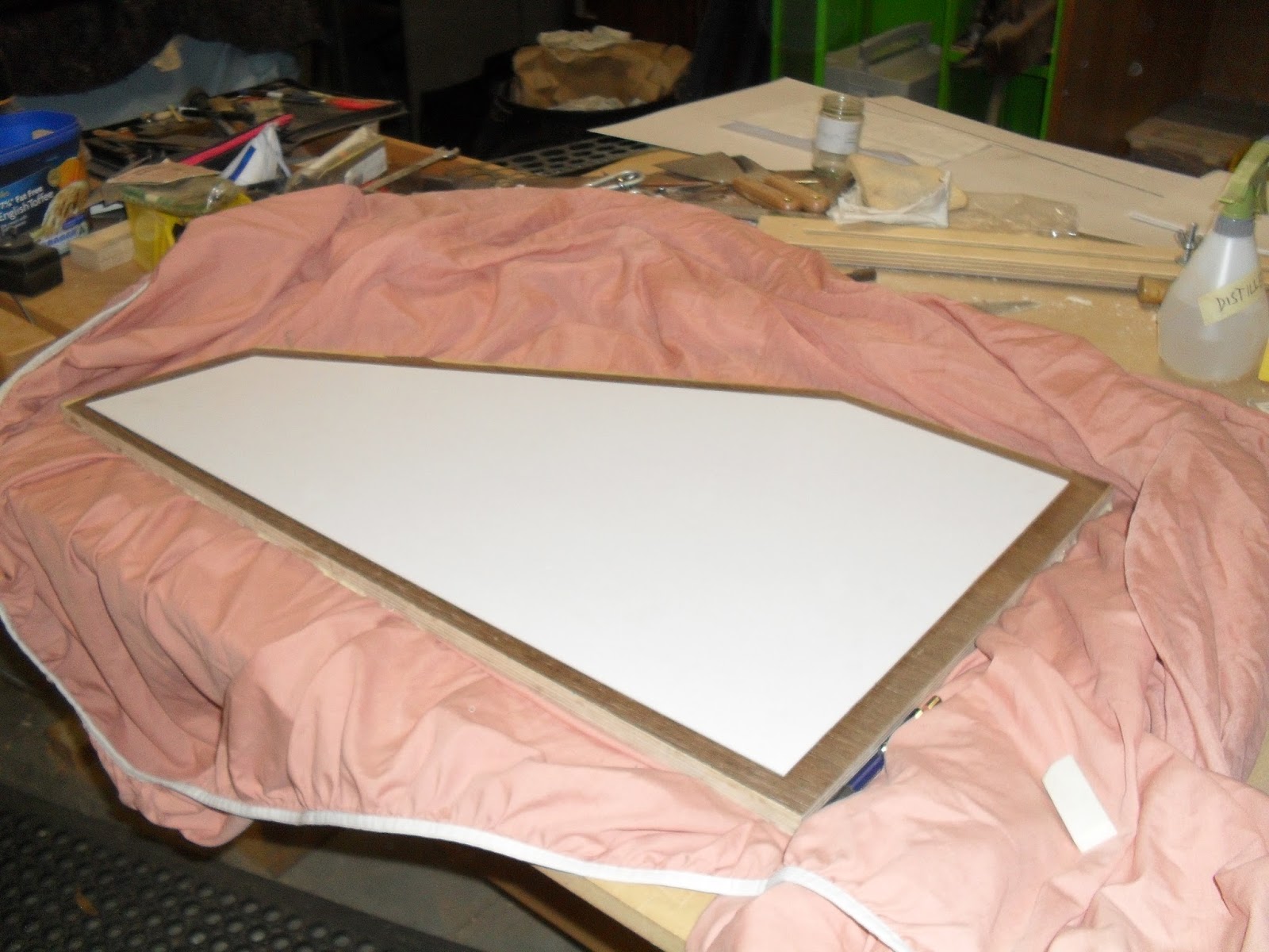
These curved lines I have talked about in one of the below pictures
To do this requires using Pythagoras theorem.
You need a sharp pencil and a tramal.

Since I needed to get high accuracy with these templates I decided to buy a lead pen with .5mm leads.


Pythagoras theorem. The diagonal line of the triangle will always be the longest edge In this case I have decided to mark up 300mm from the bottom corner of the page. I placed a line 10mm from the bottom edge and side edge to start from. At this point also mark out 400mm. The 400mm point is where I will use the tramal point to reference from. From that point to the pencil will measure 500mm.
I make a curve at where the 500mm mark lyes. I will also do this for the bottom corner point where I need to mark out the 300mm curve point. If the two points intersect, the intersection will show where the 90 deg straight line needs to go through.
This will work with any other measurement like 300mm being 600mm and the 400mm being 800mm or the 500mm being 1000mm. As long as each section is evenly spaced out this process will work.

I ran into a bit of a problem and required me to insert the angles from scratch for one of the templates. This was for the top panel for the cabinet. The thing that was wrong was that one of the drawings contradicted another. I made a note of this so it would be fixed to the final drawings when being handed in.
I find these incra rulers and protractors I bought have been very useful in obtaining high accuracy in measuring. I can actually mark out to .1mm increments. I will be using these for marking out my joints since they are so useful.

I had to re draw a few sections on sketch up to fix up the problem and up date the drawings so I would not mistake the old drawings and continue on from it.


checked all angles and measurements from new top panel drawing and transfered to template paper section.
I will probably cut this panel out last to make sure that the new measurements match up to the rest of the piece.

Working on templates for doors.


Began cutting out templates with a sharp blade. This is the drawer box base template.


Front door flap in its two flap sections.

All templates for panels cut out and ready to be used to transfer the final panel size to the veneered panels. In the mean time I will store these in the big folio case I have so they don't get damaged.

I needed a top plate for the router cutting station for the saw blade to just go into when cutting the 20mm offset from the parts.
I didn't have any other material to use for it so I had to cut down my drawing board.

The board needed to finish at 1000mm by 1037mm which was the size of the top of the router cutting station top.

Needed to make support beams that were the same thickness as the panels. These support beams would sit next to the parts and under the circular saw guide bar. These support beams would prevent flex in the guide bar when being clamped down on wither end.
I needed 2 6mm beams, 2 16mm beams, 2 21mm beams and 2 26mm beams. I cut up some ash stock that I had in my work shop that I was using for jig making.

Had to clean up some of the faces and edges by running through the rip saw and the thicknesser.

Sanded the glue faces through the drum sander.

Doing a dry run before gluing up.

Scored the glue faces of the laminates and lightly sanded to get rid of any burrs created from the saw teeth of the hand saw.

Sprayed water on the glue faces to kick start the curing process with the polyurethane than spread out the glue with the glue scraper.

Pressed up the laminates with sach clamps and 'F' clamps. These laminate jobs were for the 21mm and 26mm beams. Needed to leave for 4 hours.


Cleaned off the dry polyurethane from the laminates from the rasp on both edges. This would prevent blunting the blades for the jointer/ thicknesser.

Dressing the edges of the 26mm thick and 21mm thick support beams for the cutting station.

I'm not really happy with this fence since it is only locked in from one pivot point. Any pressure placed on the fence knocks it and makes it un square. Even this set up some times doesn't give a great square fence. The fence is quite worn.
Later on I will be putting in some effort into making a large removable fence that is a lot higher than this. Also the fence would extend from the edge of the in feed table to the out feed table. I would use a birch plywood substrate since it hardly moves. I would place a melamine board over the birch. The attachment would be screws counter sunk. The reason for the melamine is its smoother prevents less friction and can easily have lubricates added to it which wont sink into the poors of the material and alter the materials structure.
I make a sliding mechanism to the jointer fence as well and attach this to the saw table. This would allow the fence to move forward or back. I think I would end up making a similar fence to the saw as well that would run on the same sliding mechanism. Again not happy that this fence system for the saw only has one pivot point.
This fence has dis advantages it doesn't give enough fence to use on the in feed side.

Used the jointer to dress up the edges for the wenge. But wasn't giving a totally square edge so I will probably do this at tafe. I was having problems with dressing something this large on the jointer with such a small fence and a fence that only was secured from one pivot point plus the fence not being totally square when when clamped down at the other end.
At tafe they have a larger jointer that has a fence extended from the edge of the in feed table to the out feed table plus the fence is higher less worn and is secured from the central point of the fence.
The dressing for the smaller pieces was ok and did its job for what it was needed for.

Started to thickness the parts to the right thickness that I needed them for.

Used some soap as a lubricate to help the parts run through the thicknesser a lot better. Wax also works good as well. I don't like using lubricates that have solvents in it to do this since it defeats the purpose of cleaning the timber since it stains it.

I had to change the blade on the circular saw due a more finer toothed blade that was going to be better for cutting veneered panels.

Marking out the final cut shape on the top carcass panel from the template. I needed to make sure to line up the middle of the template with the middle veneer joint line.

Set up the modified cutting station and began the first cut on the top carcass panel.
I did not want to spend heaps of time in making individual clamping mechanisms this time. A lot of these clamping devices were just through of on the spot.

Having the blade slightly cut into the table top plate gave a much finer cut. Cutting into the table top slightly acts like a stop cut which will not chip out the veneer.
Close up of the cut.

Before making the cut on the final stuff I made a cut on some scrap particle board. I wanted to make sure that the blade was cutting exactly at 0 deg. I checked the cut with a square than preceded to move forward with cutting the rest of the stuff.

Top carcass panel cut to size and ready to have front edging added to it.

Cutting the off cut sections on the cabinet top.

Cabinet top cut to size and ready to have maple edging added to it.

Cutting the drawer box bases to size. Needed to remember that two are right and two are left.

This meant flipping over the template. I drew a line down the middle of the template. I needed to keep that template in the middle section of the panel.

Cutting the sides of the drawer box bases.

Cutting the back sections.

Two left bases and two right bases. I re named them on the sides since the sides would be covered with edging.

There is a little slight difference in some of the panels between one another like .5mm or less. This will be altered when the edging is added. To make the panels fit will have to slightly clean up with planers or probaly just cabinet scrapers.

Cutting the 20mm offset from the drawer box lids and also cutting in half to create the two fold flaps. Marked out all the parts using the template and .5mm pencil.

Cutting off the off cuts on the circular saw.


Once all the the 20mm offset sections were cut off was able to cut the lids in half. 10mm had to be cut away from the middle since edging was going here.

One lid section for one of the drawer boxes.


Drawer box lids all cut out. They are now ready to have the edging added to them. Like the basses there was some slight differences between one another. But this I was not fust about.
Transferring the final panel shape to the back doors using the template. I needed to place the template in the right spot to avoid the magnets. I new that there was one very close to the inside edge.

Making the first cut. The first cut was the bottom and this was going to be a 90 deg cut. The rest of the cuts was going to be 25 deg. I wanted to do all the 90 deg cuts for the back doors before doing any of the 25 deg cuts.

Used a bit of metal that would roughly show me where the magnet was located.

To make sure that the saw was calibrated properly I set the digital angle gauge on the saw when tilting it to the 25 deg mark. It says 64.9mm because this is the angle that it is coming from 90 deg. So 90-64.9 would equal to 25.1 deg which is pretty close.


The angle gauge is magnetic. Before setting it on the saw I needed to set it on a straight surface that I trusted to set it back to 0 deg. I used my straight edge.

Before doing any final cuts I did some test cuts on some scrap particle board. The angle gauge was reading at 25.2 deg.

To double check everything I also used my bevel square that was set at 25 deg. Some times its best to reference back to the old school tools. I wanted to refer back to this because I don't know whether the saw was out or the digital gauge was slightly out.

Making test cuts.

Making the final angle cuts on the doors.


More 25 deg cuts.

Accidentally nipped one of the magnets. I'm not fust about this since it will be covered with edging. I checked the teeth of the saw to see if I had damaged any of them, luckily I hadn't.

Back doors all cut to size. They are ready to have the edging added to them.

Inside sections of the back doors. There was a slight difference between the two doors but not that much.

Tracing out the finished panel shapes for the top and bottom front door flaps from the templates.
I needed to make sure that the grain matched up in the middle between the bottom door flap and top door flap section. Also Had to even out the offset sections this is so the magnets would be folding into the right placements with the other magnets. Its not that bad if they are slightly out in alignment with the magnets as they are quite strong and will still hold.

I have been thinking of making some modifications to the front door flaps.

What I'm thinking is to cut down the top section of the bottom flap and the bottom section of the top drawer flap by 7mm. -7mm from each panel will than be added back with the 7mm wide edging.
One of the reasons why I want to do this is because the timber edging creates a barrier to the wenge veneer. The wenge veneer seems to be breaking away a lot even though plenty of glue has been applied.

(Modified idea)

One of the other reasons was the small edging part that was going to need to be added to the top corner section of the bottom front door flap. I reckon this now would look un neat and would cause too much of a head ache to be kept there. There would be a high chance that it would break off.
Having edging raping around both the door flaps would look neater. Although I needed to make the edgings at the fold section look less noticeable as the blond edgings. The fold line edgings would be wenge strips. Also this would cut down another process step. The process step cut out would be the wenge strip needing to be added to the maple side after the routering.


The fold line edging is 7mm so it connects better with the other edges.
This is still an idea I will cut the other 20mm offset sections off first before settling on this and making it concrete but its most likely its going to head this way.
.JPG)
Beginning the first 25 deg angle cutting on the front door flaps.
.JPG)
.JPG)
Once finishing the 25 deg angle cutting needed to change the blade back to 90 deg to cut the bottom sections of the bottom flap sections and also the fold line sections of both the flaps. I made a test cut first on some scrap to make sure that it was cutting exactly at 90 deg.
.JPG)
Cutting off the bottom sections.


Cutting off 7mm on the fold line.

Its extremely important that the height between these two bottom section flaps for the internal straight line is the same. If out it will look unpleasant. They were slightly out which meant I had to clean up the other one to get it back to the right height.


Front door flap sections all cut to size and now are ready to have the edging added to them. I had to do some tweaking with one of the flap section joints since there was a bit of a rock ( not cut totally parallel).


Transferring the template shape of the cabinet base to the veneer panel.

Cutting off the offset sections. This panel is the thickest out of all the other panels I had to drop the speed of the saw so it would not put so much strain on the motor, blade but also would provide a finer cut. I was still using a fine toothed blade since I was cutting veneered panels.

To avoid cutting into some of the nails I had to cut off the corner of the offset section so the blade would not cut into the nails.


The center veneer joint from the top face to the bottom face was slightly out from one another. I was not bothered by this that much since the center line would not been seen since the top face has a division down the middle and the bottom face has a center rail covering it.
Removing offset from Ikebana base panel and top drawer base panel.

Transferring the final panel size shape from the template to the the panels. Now these panels have to be really spot on to their finished size according to the drawings. These panels are probably the ones that have to be the most accurate compared to the others.
I decided to transfer the image from the template to one of the panels than use this panel when totally cut out as a template for the other.
Its most important that these two panels are totally the same in size. Its not so much the front that is an issue its the back.

Beginning the first cut to the panels on the saw station.

First panel totally cut out.

This is why its so important to transfer the image to the top face, which is what I did. This face is the bottom face. The center of the veneer was not totally central. In this case I am not bothered by this since it is right at the back at the bottom and a central division covers it.

Transferring the shape of the cut panel to the next one.

Half way through cutting off the 20mm offset sections to the next panel.

Both panels cut out. There was a little bit of fiddling around to the front of one of the panels to get it exactly or pretty close to its partner.
Over all there is probably about .5mm difference in some areas between the two panels.
Cutting sides.

Clamped down the sides to remove some of the dried excess polyurethane glue. Needed to clean the dry glue off so it would not blunt the jointer blades.

Cleaning one side first on the jointer which than I can use as a refence point to place on the panel saw rip fence to slightly clean off the other side. I don't want to be taking off too much as I'm not ready to take off the off sets on the sides and make the angles. At the moment I'm just cutting the sides to their finished height which was 712mm.

The sides are currently at 750mm in length. I need to take the panels down to 712mm. So this means that I evenly need to take off 19mm on each end. I need to take off this amount evenly off each end to remove the sections that have the brads in them. Need to make sure that the score blade was turned on since I was cutting against the grain. Normally I would also mask the edges with painters tape to prevent even further break out but this was not needed since I was doing inlay edgings around the bottoms and tops of the sides.

Sides are now cut to their finished length.
Cutting drawer divisions.

Needed to remove the excess glue from the sides of divisions before running over the jointer to avoid getting the blades blunt.

Since the grain is going the other direction with the veneer there is a high chance it will split out heaps when running over the jointer blades. So to act as a break point I used painters tape to top the veneer from splitting out. I only wanted to dress one edge to get it square and flat which than I could use as a reference point up against the rip fence on the panel saw.

Running over jointer to clean one edge.

Like the sides I had to evenly take off the same amount on each side. The panels were measuring at 136mm. I had to finish them at 96mm. I was only riping the panels to their finished width as they are not ready to cut the length yet. I had to take even amounts off the sides since to remove all the brad sections.

I was going to cut the the angles for the sides on the panel saw. I was going to cut the back angle which is at 43 deg but this is not possible on panel saw. The max the saw can go when angeling is 46 deg. To get 43 deg cut I need the panel saw blade to tilt at 47 deg.
The reason for this is because you need to make up a 90 deg angle. 43 plus 47= 90 deg. If I set the saw at 43 deg it would be making a cut of 47 deg despite if cutting on the rip side fence or the cross cutting fence side.
I was talking to my teacher who gave me a few possibilities. There is an angeling cutter head for the spindle moulder which I could achieve this cut for the sides.
I had though about maybe cutting this angle on my festool circular saw since I can tilt my blade to 47 deg. I will need to still make some test cuts to make sure this is possible.
I was also thinking maybe making a packing strip to place down on the sliding bench to just pack it up a bit to achieve that angle. I'm probably going to have to go back to the drawing board to figure a few things out if this does not work.

I did a test cut on some 12mm mdf to see whether I could obtain the 43 deg angle I wanted for the back joint for the sides. I was able to obtain the 43 deg.

I taped the cut test side pieces to the base to see how well the joint went. There was a slight gaping this may may be because the cut maybe slightly off 43 deg or the base might be slightly off 86 deg.

The back point is a very sharp point. Even though this is the back of the cabinet. The cabinet is meant to be a central room piece where you can walk right around it. I have though about it maybe cutting the point away and adding in a fall piece of edging. There would be nothing worse than having this edge damaged later down the track when the whole cabinet has been finished.

There was some over lapping from the base but this was because some of the sections had not be cleaned up yet. The overlap was .7mm. Also there was some gaps with the side test piece and the base but this is because the base outer edging has not be cleaned up yet.

A slight gap in the joint but this will change since this is not clamped up yet.

I tested how the Ikebana base panel went in. It actually went in quite well. Even though the test sides are not the right thickness I moved the panel 9mm away from the sides. ( 9mm + 12mm= side thickness= 21mm). I needed to move it away from the sides this much to see if there was 16mm plus at the front of it for the back doors. The front gaping was about 16mm-17mm.

Even though it was not clamped up yet and the gap would decrease even more I had a slight gap between the edges of the panel and the sides. But this gap was not too big hardly anything. The reason why I chose to have wenge edging around the base and wenge inlay on the sides above the panels was to discuss and hide gaping if there was any. Also when the tops and the real sides are put on they will create shadows and hide it even more. A lot easier to hide a gap when its surrounded by a dark colour compared to a blond back ground.

I will cut the back first before cutting the front just encase I need to make the cut again.

Before cutting the 43 deg bevel joint at the back of the sides I needed to clean my festool saw blades. Cleaning your blades will extend the life of the blade before sending it off to get sharpened.
There are a few different ways to clean them this way I'm just soaking the blades in some citrus cleaning agent for about 15 minutes. Leaving it soaked for about 15 minutes will break down all the dirt, resins and gunk that is stuck on the teeth and sides of the blades.
You can also use oven cleaner as well for more stubborn gunk build up.

After the 15 minutes is up ( the 15 minutes is just a rough time. The more gunk build up the longer you should leave it in.) You want to scrub the blades. Use the green kitchen scrubbing sponges. Don t use steel wool or metal scourers since they will damage the blade.
When cleaning the teeth you want to scrub in the direction of the teeth. To get into smaller areas I used a tooth brush. With the amount of scrubbing you will create soap bubbles. Just spray this with a water spray bottle.

Now the important thing is to get rid of any water marks. I removed most of the moisture from the blades with paper towel. To get in between the teeth use a hair dryer.

Making the 43 deg cuts to the back sections of the sides. Once this cut is made than I can begin to router out the inlay sections for the wenge stripping and maple stripping. ( wenge strips located inside and maple strips located outside.)


The slat is at 31mm so I needed to use a better blade than the fine tooth blade which I have normally been using to cut the veneered panels. The blade I used was just the standard blade every day blade that came with the saw. I made sure to clean the blades to get a better cut.

Just did a rough dry run to see how well it went together so far it seems like to goes together well. This will be further looked out when doing the final cut to the back and when making the dowel connections at the bottom of the base.

Marking out the router housing for where the inlay strips will be going. ( this is further talked about in the post for inlay to sides.)

Once all the inlay sections were glued and dry I just need to clean off 1mm from the back edge. The back edge needed to be clean so I could use it as a reference point when running it up against the panel saw rip fence when cutting the front. The front angle of the panel was 72 deg which meant that I had to tilt the panel saw blade to 18 deg.

I taped the bottom section to prevent blow out.

Unfortunately the first cut did not go well. I made tests to see if I was cutting at 43 deg which I was but what I needed to do is do a rough mock up. In the drawings it says that the back angle is 86, infact the angle on the panel ( due to human error) is 85 deg. This means that instead of cutting the sides to 43 deg at the backs they needed to be cut at 42.5 deg.
This is the problem with angles. When I made back sides to 43 deg it was leaving too much of a gap due to the back angle of the panel being 85 deg not 86. A little human error can throw everything out especially on a large span.

After I was happy with the test I went back to fix up the backs of the sides. This meant that I had to cut down the panels by an extra 1mm. So instead of the outside maple inlay measuring 16mm wide they were 15mm wide.


I taped the back to see how well it would go together. There is a small gap but it seems to close when pressure is placed on it. This will be further looked at when machining the dowel holes in the base of the sides.
No comments:
Post a Comment