
I'm going to need a proper clamping device system for cutting the edges of parts with the circular saw. Some parts will just be cut straight others have cut angles made to them. The jig system will also be used for routering as well.
Now this is just a rough concept and may change later down the track for modifications but this is pretty much basically what its going to look like. Again keeping jigs as simple as possible.
I wanted to make a jig table system in which could stay on its on for further use with further parts so it would be separate from my main work bench.
As well later down the track will be placing 90 deg lines in certain sections this will allow me to create a compas effect with one of the sliding clamp beams. Basically it would pivot from one central point that is at a right angle and can be placed at any deg with in that 90 section. Also could place a central point in the middle allowing to be placed at any angle with in the 360 deg mark.

We have hard rubbish around my area where my workshop is located. I found this rusted metal framing that would be perfect to place the jig table top on. This will allow me to use for other parts in final piece as well as further projects after this down the track. A great find since this will save a lot of work. Ill just need to put it on industrial casters so has moveablity in my work shop.
The old saying ' one mans trash is another mans treasure'
Will probably place a shelve on the bottom and later down the track add drawers and probably a built in power point. But at the moment im just focusing on cleaning it up and a table top for it. Those other elements will come later down the track.
Will be making the jig out of plywood board a lower grade compared to the substrate. Will be running cross beams down the middle for extra support for the top to prevent further movement.

First thing was to remove the rust with just an abrasive pad attached to a hammer drill set on a high setting. Can also use an angle grinder. And an iron brush to get into the tighter areas.


http://www.justtools.com.au/
Just got my new toys for the next stage in the final piece. This is the circular saw I'm using to cut the 5mm offset from the parts, to cut the 20 mm veneer offset, and to do some of the angles. This is a very high precision circular saw. I also bought a miter gauge attachment for it that connects to the guide bar. This will be perfect for cutting the sides that are at unusual angles.
Bought an Aluminum blade for the saw as well. This will give a finer cut when cutting the substrate when veneered.

The whole saw gets stored in a protective systanier. The bottom case that has the accessories attachments can connect to the main saw case as well, making it wonderful for carrying.


Bought another sized guide bar for the saw which was 1080mm. The one that came with the saw was 1400mm. This is what the saw will be running on when making cuts. This will insure I obtain a straight parallel cut. The first cut when using the guides will cut into the plastic stripping that acts as a grain break to prevent splitting on the good side. If you don't want splitting on the off cut size there is another chip break attachment which I have also.
When cutting anything its always best to obtain the right speed for the material your using. Will be starting off on speed 6 and making adjustments if needed.
The thicker boards im using will be making the cut in two passes (this creates less strain on blade and keeps blade cooler, you will also find that you will obtain a better finish.). As for smaller part sheets like 9mm will be doing in one pass. If its one pass or two the last cut should just be slightly sitting below the thickness of the job. This does a couple of things, extra safety, puts less strain on blade, prevents less splitting.

The clamps slide under the guide bar and secure the guide bar and part to the work bench keeping the clamps totally out of the way.


Can change to -1 deg up to 45 deg.
Next stage is to build the rest of the work station for the saw to be used on for the parts.

To further protect the metal framing needed to coat it with a rust guard epoxy enamel coating. Decided not using black mainly because thats all I had at the time. Just applied the first coat. Ill only need two coats. Have to wait 4-6 hours till I can apply another coat. Before I apply another coat will cut back first (sanding)
With this type of Epoxy Enamel Rust Guard need to give it a good stir about five minutes before applying it to the piece and keep stirring in between the job.

First had to remove all the dust, dirt, and any other grim before I applied the first coat. Lucky it was a hot day so I gave to a good wipe down with water and a rag.

Mid way through first coat.


This is the basic design of the saw/ routering station I'm making. The top metal plate is the saw guide that the saw will run on that I just bought (pics above). I have already obtained the metal framing and are in the process of cutting back and applying the next coat of paint.

These were the toggle clamps idea I talked about before that we be secured to the adjustable sliding beams that will run on trenches from a bolt and wing nut connection. The beams will have a housing in them that runs through both sides same with the table top. The table top will have slip mate placed on it for extra grip.

To be able to have the ability for the guide bar for the saw to adjust across the table very easily. I have though about making a slide mechanism that runs slightly on the same principals as the slide beams that the toggle clamps sit on. The sides of the table will have have boarding connected to it that has a housing in it, just on two sides that run on the y axis. Also there will be strips of acrylic housed into the sides which will be glued down with araldite glue. The acrylic will help the slide connected move more freely. The slide connector will also have a housing in it that meets up with the boarding housings. To locate them in place it will run on a bolt and wing nut locking system. This will make allow for quick and easy adjustments.
The guide bar for the saw has trenching under it. Now there are special clamps that go under the guide bar that connect into the trench. The extra lipping on the slide component is basically a clamping block that allows the clamp to clamp the guide bar to the table slide connection system.

Probably will add slip cloth to the clamp block section that will prevent clamping damage.

This is basically what the saw/ clamping table system will look like.

Pieces of plywood will be used to connect the casters to the framing. I could weld the casters to the framing but I don't know how to weld so this was the other alternative. The casters will just be screwed to the plywood and the plywood attached to the metal table framing with L brackets. Plus If I'm wanting to add in a bottom shelf later down the track this will make it a lot easier to attach one to it.

To get even better accuracy thought about attaching a ruler to the actual side frame (just glue it down with araldite in a shallow housing. Although I wouldn't be using a small ruler like this. Ill be using a meter ruler. Since the table length is only 900mm I'm ok with having 50mm over hang on each side.

Decided to buy some 19mm Hoop pine plywood sheeting for some of the jigs. I didn't want hardly any movement in he parts since the jigs needed to be highly accurate so had to pay a lot, but in the end will be worth it. I didnt want to use MDF since with the jigs will be doing a lot of screwing, plywood screws better into than MDF, (Also stated reasons from previous pages).
With some left over this will cover the parts for the router/ saw jig table and the spline saw jig.

I only needed one sheet for cutting out the parts for the jigs. So far at the moment I was going to need to make jigs for the saw/ router jig table and the spline cutting jig.
The plywood I used was Hoop pine plywood which was 19mm in thickness. This is a great plywood for jig making since it has limited movement which is what I needed in the jigs. Once the jigs are made I'll be sealing them to prevent even more movement.
(followed the same machining processes as when cutting the birch plywood)

Remembering to mark off the parts that have been cut on process layout cutting sheet and marking them with chalk.

Panel saw at work which I cut the Jig parts on from the Hoop pine plywood sheet.

Placed where the sliding trenches were going in the table top for the saw/ router cutting jig table. Also place where all the slip matting was going to go.

The masking tape is not needed so much since its cutting with the grain. But this is just a further precaution. Ill be making 10mm holes at the end of each of the trenches. This will allow me to either place a jig saw blade inside or use a router bit. Either way will have to run both off a fence. As well will need to place masking tap on the bottom where the cut is being made as well. The masking tape is just acting as a grain splinter break.
Id like to use the Festool jig saw at tafe since it works very well (pretty sure they have one). The jig saws I have are crap. If I cant obtain a good jig saw will using the router approach, just will have to do it in a few paces.

Working off the table top drawings, having them close at hand while I drawer in connection points and other info.

Marked out where the sliding trench is going as well as where the screw holes are going to attach the side slide bar to the table top, these will be clearance holed. Also marked out where the acrylic trenching are going to be where the acrylic will be glued in and used as guides. The acrylic I'm using is about 4mm thick so the trenching will be about 2mm in depth. The trenching is 20mm wide and will run to both ends of the part.
Will place in trench for ruler later on.

Markings made out for both side slide bars.

Markings made out for the slide mechanisms that the saw guide will attach to.

We didn't have any forstner drill bits at work so used another approach to make the clearance holes for the ends of the trenching. Just used the tip of a spade drill (didn't have the right size spade drill either) and taped a small hole in the specific location with a hammer. All I'm doing here is creating a locater for the drill bit to full into when drilling into the parts on the pedestal drill press.
To prevent blow out I used masking tap on the back. If I was using a spade drill or forstner bit due to the point when Id break through the back with just the point I'd flip the part over and finish off the drilling from the other side, using the broken through point as a locater hole. Doing this would prevent blow out. But since I don't have these drill bits masking tape will do. It doesn't prevent all blow out but most.


This is what I meant by clearance holes at each end of the trench. This will allow me to drop in a router bit or a jig saw blade.

Parts with clearance holes made in them.
Some of these parts I will have to use either a router or a jig saw. But what I'm thinking with some of the parts I might be able to use the mortiser at work. Will have to test this as Im not sure how much break out will happen. I have the 10mm mortise bit to use. May have to drop down oscillation of the machine to a smoother machining speed. Also place masking tape at back to act as a grain break and maybe attaching a scrap piece of plywood to the back acting as a further break.

Made clearnce holes for screw sections. I just used a 5mm drill bit on the drill press. I also placed counter sinked holes where the screw heads were going to provide flush surface with the jig.

I didn't bother placing masking tape on the back since that is where the counter sinked holes were going so any small split out would go away.

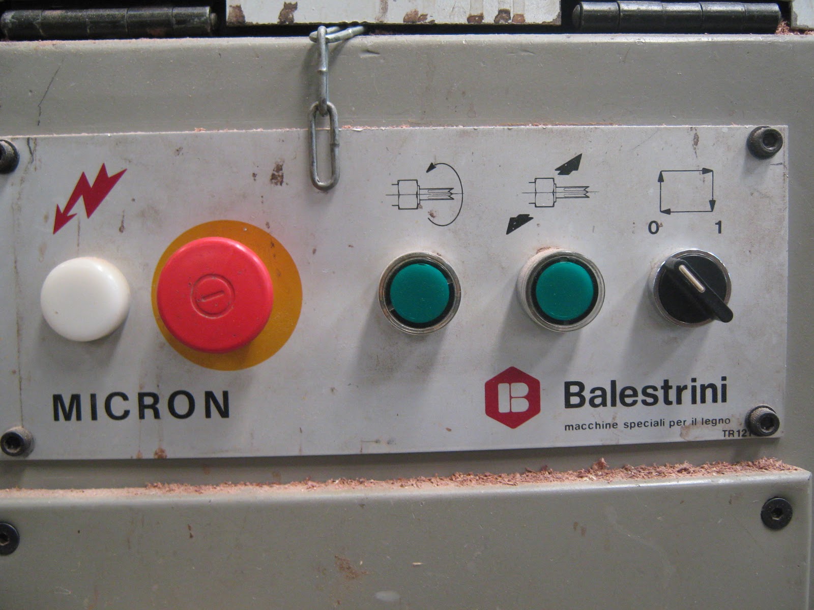
So with a mortise basically you have 4 switches on this one. The big red one is just a stop button. The first green button on the left starts the spinning of the cutter. The next green button begins the oscillation of the cutter. ( basically cutter moving from side to side, which is what makes the length of the cutter.) You change the size at the back to determine how much oscillation there will be. Now there are a few things to remember when creating sizes. Lets say I want a 50mm long mortise and I'm using a 10mm cutter (which is the same cutter I have in now for this job) On the sizing gauge you have to take off 10mm from the mortise size you want due to the 2 5mm radius on each end. This is like a router bit its not designed to make a square hole it will only make a curved eclipse hole.
Now you can get square mortises this is achieved through a mortise drill press which I want go into detail with it that much but basically it has a square cutter and inside the cutter is a standard drill bit which removes the bulk of the waste.
The next which is a station position which which means the machine will be left on but nothing will be moving basically a pause button or a feed hold button. This is great for when your getting more parts to machine from your material trolley or removing already machined parts from the machine work station.
This machine is great for doing jobs that require a left and right set up. So the feed hold switch does come in handy when your doing a lot of this.

This allen key adjustment here alters the height in which you want to raise the stop to depending on the height of your work. When machining stuff you want a clamp to secure the work down while its being machined. The other handle moves the stop in and out. You generally want the stop to be placed in the central oscillation point of the mortise bit. Or if your using small parts generally in the middle length of the part.
The mortise and the tenoner we use work on airomatics, mechanics and computerization.

This is the size gauge I was talking about thats at the back of the machine. Now to access this you need to remove the hood of the machine. Now when adjusting machines should always turn the machine off from the wall. One cool feature with this machine is that when you lift the hood off it automatically kills the machine since it lifts of a power switch. Even though this does this Im still in the habit of turning off the machine from the wall. To adjust this you need to loosen the top Allen key bolt and than there is a side Allen key bolt on the left that allows you the adjust the sizing. When you have set up the hole sizing lock everything up. Now to get the correct starting position you need to move the whole wheel to the exact starting point of the oscillation which will be further towards your self when your at the back of the machine. Move it clock wise will allow the cutter to move away from you move anti clock wise the cutter will move further way from you. If you make a full clock wise turn or anti and keep doing this it will just keep running back and forth on its sized oscillation. I tend to drawer out where I want my mortise to be and use a small block to line up the edge of the cutter to the edge of the drawn mortise that is closer to the back of the machine. You want to align the edge of the cutter that is closest to the back of the machine.
The steps I do first when setting up the mortise is change tool bit if I need to either if its too big, or small or is blunt. Than I change the size length of the mortise.

So as you can see the back wheel moves the oscillation of the cutter.
The clamp adjustment runs on long bars so you can machine many different height parts. The biggest I have done has been around the 400mm-450mm mark.

Now since dealing with ply I needed to drop the feed speed of the machine. Now What I mean by this is that the machine is still spinning the correct RMP its just the feed rate of the table moving into the job is lowered. The tool bit does not move into the the job the table moves the job into the the bit while its spinning/ oscillating. This was to prevent grain splitting. I still put masking tap on the back of the blow out section. But after running one I found out I did not actually need it. Plus also the sharp cutter helped as well.
Since these were long mortises I only set my oscillation set up to about 40mm. Since the board is only 19mm there isn't much surface area for it to sit on the work plate as well as much surface area for it to be clamped I had to make small cuts so the part wouldn't move when being machined while clamped. Having a bigger oscillation will have greater chance of making the part move since its trying to take out a greater amount of waste.

Think of it this way OK I have a long cutter so ill move the outer bolt inwards away from the sensor plate so its home position is going to be further out from the machine. Or if I have a shorter cutter ill move the bolt outwards. Now I want to adjust the depth of my mortise more so ill change the hangout of of the first bolt so its either closer to the sensor pin or further away.


You don't want the cutter to be hanging too much out from the exit point. This this will cause more heat and strain on the bit also could have the chance to move the part more when its clamped down, also could cause major splitting.

Both ends of the machine are connected to dust port pipping that takes majority of the waste to the dust extraction bin. The red switch at the bottom is a major kill switch button in case something goes wrong.

You can set measuring bar stoppers at the front of the work plate or at the back. Im mainly use to setting it up at the back. For this set up I didn't needed a stopper. You will set up the stopper to the work piece when setting up the starting point of the oscillation sequence of the cutter. This is what I also meant with setting up the block to the outer bit of the cutter to the end of the mortise closest to the back of the machine. This is the third thing you do if needing a set up stopper. The fourth thing will be getting the right placement of the cutter in the Z axis determining whether your having an offset mortise your whether its going into the middle of the job thickness. The Fifth step will be getting the right depths by adjusting the bolts in accordance to the sensor stop pins.

See what I mean by little surface area for clamping.
You can also see a little air hose near the clamp. What this does is when it has hit the left sensor pin which means that it has finished its job and is going back to its home position than let the other side start up it will blow out air to remove the dust that is created keeping the work plate clean. I still get in the habit to blow the dust off when doing each part as it builds up a bit. Dust build up will alter your set up if you don't remove it.

Since there is no measuring stopper used here you have to be so careful where you place your hands and where your wanting to cutter to finish machining. A lot of this is done by eye.

Parts all machined up for both router/ saw jig table and spline cutting jig. One of the parts I stuffed up earlier from the drill press, placed the locater holes in the wrong area about 5mm off. Woops!!!!!

Now I needed to make 10mm diameter drill holes in center part areas of the table top for locater holes for a router bit to sit in or jig saw blade. I couldn't use a drill press. I could have used a standard drill but I wanted to get a true 90 deg straight hole. So I decided to buy this.
What this is is a Drill guide that allows your cordless or drill with a cord to be attached to it to make straight holes in the center of panels where you need accuracy and can not use a drill press.
Honestly I have not used such a piece of shit, luckily I didn't pay much money for it. I reckon a little more effort they could have made a very useful product. So like most times I will have to modify it. The tool guy I was talking to was right its a great tool but I wouldn't not pass it down onto my grandchildren.

Also bought my toggle clamps that I need for the jigs as well.

It is very top heavy and rattles around too much. There are screw pins that hold it down (not really that good) the only good thing they do is scratch your work well.
What I'm thinking is Ill make another base for it and drill a hole in the center of it with a large borer drill and than mark in the cross heirs on it in connection to the ones on the drill base. Than I would connect 4 toggle clamps to it that would secure the whole drill gauge to the actual job so you than can use two hands to lower the drill instead of one and having to hold the base down. Ill remove the screw pins and place a bolting system that will bolt the drill gauge to the plate.
Although I'll think about doing this later since I don't think ill need to use this for any more stuff in this project. Plus I would need to buy 4 more toggle clamps. They don't cost that much about 15 dollars for each one. Plus also I think I would need to make a more secure support system that holds the bars up a bit better they are a bit flimsy.
Although I like the fact that I have ceiling power points as well in my work shop this tool works really well with them.

The drill gauge can be set at different angles. I actually found the angel set up ok. To test whether it was true I used my angel gauge. I set the zero mark off from my machined straight edge which I sat on my jointer table since I know that this is quite accurate since I had just previously set it up with the straight edge and feeler gauges.

The top part said it was .3 Deg out

The side bit said it was out by .1 deg so over all I was quite happy.

The only annoying thing with this set up is that secondary drill attachment built into the jig doesn't hold large drill bits. Would not even hold my 10mm diameter drill bit. There are attachment components you can get to get around this although I didn't have any in my work shop sadly. So want I did instead was use a 3mm drill bit which acted as a clearance hole. Than after that I would use the 10mm diameter drill bit in the drill on its own to finish off the job.

Used a nail and a hammer to make locater holes since again did not have fostner drill bits and could not find my fine nail punches at the time.

Once made the clearance holes marked off the backs with masking tap to avoid blow out.

double checked with the calipers whether it was 10mm. Not a huge big deal if it wasn't but I'm stuck in this habit.

Had to use a totally different drill since the 10mm would also not fit into the orange drill bit as well. Carefully centered the drill and drilled the rest of the drills. Packed up the table top since did not want to drill into the work bench.
The table top is ready to have the rest of the trenching drilled out. I'll be doing this at tafe with the jig saw or router. Id hopefully like to get some of the parts sealed out tafe as well but we will see what happens.

Had to check the angle of the saw to make sure it was cutting at 90 deg. Since cutting span rails for the saw/ router jig table frame for extra support which ill be placed between the slide trenching. 89.9 pretty close.

Just put on the second coat of paint to the framing. before this just lightly sanded it.

Had to rip the parts from scrap. Excuse the unsafe saw in the process of buying a new guard. This is on my multi combination machine in my own work shop.

After this just thicknessed them to size which was 30mm by 30mm the length of the span rails were 723mm.

Made slits at the edge of the trenching sections on the panel saw at tafe. I did this because it acts as a grain break. The trenches had to be rebated out. About 2.5mm in depth.

I always rule a line where I'm wanting to make the cut set the fence on the saw and just do a dry run. What this means is just running the job on the saw if you were cutting it but without the blade on, This will show you whether its going to be cutting in the right spot. You don't need to run the whole piece over you only need to just tip the edge where your drawn line is on the part.

All groves made on parts for where acyclic trenching is going.

Always turn off the machine at the wall or get in the habit of removing the plug from the power point when making adjustments or changing router bits. I decided on using a 18mm straight edge router cutter to remove the waste from the trenching. The left over waste was 17mm and the trench was 20mm so this was a great cutter to use as I would not need to do two passes.

Since the opening was to big for a set of calipers to rest up against the table and top of router bit I had to measure 2.5mm on a piece of timber and by eye raise the hight of the router bit from under neath the work top from the router the the drawn line.

After setting the hight of the router bit I set up the distance of the fence to the outer edge of the router bit to the right positioning I wanted. Normally I would use a ruler but cant really obtain a proper measurement with it in this circumstance. So I draw on the edge of the part as to where the rebate was going to be placed. Just Just made sure that the router bit was only going to remove the waste part section. So in this circumstance from the fence to the outer edge of the cutter it needed to be 17mm.
This is one reason to add in a scribe cut first to avoid slitting. Even though it is going with the grain and the router bit was sharp always best to take precautions.

Originally I was going to set up another fake fence like this. To do this I just got small piece of really thin plywood about 1.5mm and placed them on the parts I was going to router than place the extra fence on top than clamp down to the main fence. The thin pieces of plywood would be acting as spacers.

Decided not to do this and decided on using the feather board which was located under the upside down router work station top. The good thing about feather boards in this circumstance is that it will keep the piece totally flat while being passed over the cutter. Also the feather board will prevent pieces from kicking back when feeding them over the router. Now you need to place the parts from the right since this is in the correct direction of the the way the router bit is spinning.
The feather board is just a board cut on a slant that has had kurfs made through it. While passing it over the router bit it will press the piece down. You can set it up the other way by wanting the piece to run totally flush up against the fence or can do it both if requiring the need to be pressed totally down and totally up against the fence. If wanting to pull the piece back due to the friction caused from the splines on the feather board to the piece they act as a break.
You don't just have to use these on upside down router tables you can use them on sanders, moulders and saws. The feather board was made before the invention of the feed roller. Even though this is an old tool it is still used a lot today where a feed roller can not be applied, plus its cheaper and just as effective.
There is not or very little spacing between the feather board the the actual piece you are machining. I tend to just do a dry run first to see whether the piece is going to run against the feather board and work plate well, without any force needed or not having too much slack.
Always make sure there are no wondering fingers.

Always do test runs on scrap before doing the real thing. I measured the depth and it read about 3mm. I wasn't too fust since they really didn't need to be super accurate. The main thing was that I just wanted about half of the acrylic to be poking out of the rebate and all the rebates to be the same depth. A feather board probably wasn't needed so much in this circumstance since it was a very shallow rebate and not much waste was being removed.

The rebate read about 18.6mm. Some of the reading wasn't correct (20mm) since there was a little bit of waste still in he rebate that needed to be removed. I decided on paring this out with the chisels. The waste left over closest to the edge I did a second run on the up side down router table. The little bit of waste was to the internal edge of the rebate that I needed to pare out, this was roughly about.5mm.


First run of rebates, still need to remove waste left over.

Close up shot of waste left over.

Even though your using a feather board you will need to apply even downward pressure and inward pressure towards the fence. You don't need to force it, just guide it.

Waste removed from outer edge.


Best to clamp down piece so you have more control with the chisel while paring.

Best to have very sharp blades since acrylic splits very easily. And also have a air gun close by since that particles made from cutting the acrylic don't easily go up the dust shoot and don't easily move off the work station.


Routering the trenching slots in the table top.
Clamped down the top to the work bench and clamped a fence to it as well that the router would run up against. I needed to measure 75mm from the edge of the fence to the outer edge of the router bit which was in accordance to the outer edge of the trench drawn on the top.
I had to do 3 passes on each trench. I was only using a 10mm straight edge bit so it didn't have to strength to take out the waste on one go. Plus you will find that you obtain a far better finish when you do it in a series of runs. The drilled locater holes were very good idea.
I set the router on top speed for this which was at level 5.

Any chance you get always use a vacuum dust extractor prevents dust getting in eyes and lungs. Plus keeps the floor clean and prevents the chance of slipping over. Also clean up is halved a lot.

I just made a very shallow cut about .2mm to see whether my router was going to be routering in the right location.

I used the plunge action with this made things so much easier when machining. Now you need to be careful when coming to the finish cut. Make sure you raise the whole router bit out of the trench. When turning off the router since it has such a huge stop break the router can jolt and nip the edge. Best to lubricate the plunge bars. This is to just prevent friction so the router can go back to the home position without any effort while its still going before turning off.
Another way to prevent this is also siting another fence on the other side of the outer. This will make sure that the router wont go left or right only straight. Try and wear the dust pipe and cord around your neck like a scarf, dont rap it around just let it rest on the back of your shoulders. This will keep the wiring and piping totally out of the way. I just couldn't do it here since the pipe was too short. If you have those over hanging wire/ pipe stands than use them as they are fantastic.

This is so it want create heaps of splitting, and wont put heaps of strain on the router bit.

First trench made.

All trenching made.

Started to sand the parts for the jigs at my work shop. I didn't need to do heaps of process sanding so I just hit the parts with 240 grit. I only wanted to seal the parts to prevent further cracking or movement. So a high desired finish wasn't needed. All the edges had them slightly broken ( small bevel)

The edges where the trenches were also had their edges broken as well.

As for the top I started off with a 120 grit than worked up to a 240 grit. Compared to the other parts the top needed just a slightly better finish. But again like said before not after a high finish. Edges were also broken as well.

Did the last sanding on a scrap bed cover to prevent scratches. I'm thinking later on I might invest in some good quality blankets to keep the veneered parts wrapped up in when waiting for next stages in making process.

Internal cross rails were sanded and edges broken. These will also be sealed as well.

Applying first coat to top. Before removed all dust from sanding.

Applying first coat to other parts.

All parts finished first coat on the top. Now to flip over and do other side. Wait 30 mins for touch time. It was a nice warm day while I was oiling so the parts dried very quickly.
Keep stirring the oil while in applying stages. always do a big stir before the job, never shake the tin. Just use a paint stirrer ( this can simply be an oil wooden spoon or an old wood ruler or an off cut from the work shop)
 \
\
Applying first coat to other side. Placed drying parts on small offcuts to keep off table to keep clean.

Finished up first coat to faces and edges. Will start second coat after light sanding about 240 grit.

To avoid oil build up on the seal section of the can when drawing the brush against tin to get majority of the access oil off punch holes into the seal trenching with a flat head screw driver. Doing this will allow the oil to seep back into the tin which makes the top section more cleaner and easier to open the next time you use it.

I used a water based polyurethane satin. I don't usually use water based that much more oil based. So this was new for me I found that it dried a lot faster compared to a oil based one that I have used in the past. This meant that I had to work faster in getting the alignment of strokes with the timber grain. When working with other oils you tend to have a little more time to come back and fix things up. ( but this depends on also the temperature)
With the oil based polyurethanes I tend to mix some turps with some in another tin just to thin it out so its not so thick. While I brush it onto the timber I used a white cotton rag bunched up in a shoe shape and run down the grain of the timber where the oil has been placed with the brush to thin out any streaks, bubbles and getting the oil neatly spread out running into the right direction.
When using oils you wanted to us a brush that is designed for oiling. Brushes for oiling will have a sharp tapered tip. When oiling with a brush you don't want too much on your brush. Thin applications and run the brush in the right direction of the grain. You want to try and keep everything in a straight parallel application. When moving across a board when you have made one width application streak, the next one you want to over lapped the last one by about a third. This means that everything will be totally covered and you wont miss any sections.
Work at one section at a time and be patient rushing it will just stuff things up. When using a brush for oiling or even painting when starting off you want to come in from the edge about 10mm to avoid the brush lapping the edge and causing access oil or paint to run down the edge. At the other end of the board you just want to gently take off from the edge with the brush. Than go back to the other edge and come in from the other direction to cover the 10mm. Doing it this way will keep things neater.
This is just a very basic way of applying oils there are many other ways that will give better and different results.
If your serious with oiling. By a good quality brush. Buying a good quality brush and taking care of it you should be able to use it for years and years.
When you have cleaned a brush try to get in the habit of drying the brush out and wrapping it in butchers paper. This will clean the brush clean and neat.
Each coat is about 2 hours waiting time and touch dry is 30 mins. ( but this also depends on the temperature).

This is what the holes should look like you don't need heaps about this amount is enough.
Cleaning up the brushes just had to soak them in some hot soapy water in a jar. I washed most it off with soap with hot water and a brush. Some of the particles were not coming off so i decided to soak them over night and clean the access off the brushes the next day.

Sanded parts before applying the next coat just used 240 grit. Sanded all parts on an old bed sheet so they wouldn't get scratched. Dusted off dust with brush before applying new coat.

Applying second coat to top face and edges. Used a small sponge to remove access.

Finished applying second coat to top faces and edges.
Waited for 30 minutes than applied second coat to other face.

Finished applying second coat to bottom face. Need to leave for 2 hours before applying next coat. Will be sanding again before applying the third coat (which is the last coat)


Just applied the third coat to the jig parts for both the saw/ router cutting station and the spline cutting saw jig.

After the third even though it wasn't really needed I wanted to apply some polish to the parts. I just wanted to practice with this since it was a sort of wax coating and I have been thinking of applying this to my final piece when its finished.
I used this little technique that I had read up about a while back when I used to do a lot of oiling on projects. What you do is use a cotton white rag (should always use cotton white rags for oiling or even staining. Some times colored rags the oil reacts with it and can form unwanted coloring on your projects). With the rag you place a square cut piece of car sponge. Now you want to use a totally brand new car sponge since it wont have any grit or other dirt particles that will effect the oiling process.
You want to fold over the top and bottom sides than the sides you want to fold in than tightly twist. Once you have the right tension tie it off with an elastic band.

I found oiling with this made things so much easier you could spread the oil outer better to avoid streaking from the brush. Although this really worked well for the polish since I found it a wonderful way to really buff the polish across the parts.

What I did was placed a bit of polish on the rag bun than rubbed in a circular motion with a bit of pressure and really fast than I rugged it all back in the direction of the grain again going really fast and with some pressure. This made sure all areas were going to be covered.
The polish I used was an Australian made one. Has lemon added to it and really smells like soap. It gives off a really nice pleasant smell. (will add in specs later)

After that I rubbed back with steel wool. I only did a quick polish job on this along with the oiling. Heaps of care wasn't really necessary since it was only a jig and over time it will get bumped and knocked. This process was more just to practice but as well further coat the jig parts as well.
This sponge bun thing is great for applying oil. Due to the sponge it allows you to soak in and squeeze out what ever amount of oil you want or don't want. Makes things so much easier.

Started to place parts on large drop sheets to protect the sides. I only did one coat of polish to the parts and surprisingly came up really smooth and nice. I reckon this would be a good product to think about using for final piece or something similar, will look good when more coats are added.

Marking out location points for the span rails for the under carriage for the table base frame as well as the other connection points for the brackets to attach the table top to the base.


starting to assemble the connection brackets to the cross rails. The span rails where merely for just more support but also to prevent the table for buckling over the years.


For further connection points was adding in figure of 8 connector holes which I just used a 18mm spade drill bit. You only want to drill the hole to the half point of the eight and you only want to go to a depth that is the same thickness as the figure of 8 connectors.

Figure of 8 connectors added 3 added to each cross rail.

So I could get the placement correct while screwing the cross rails connection brackets to the table framing I used a sach clamp, this prevented movement which made it a lot easier to drill the screws in since I didn't need to hold it. Before screwing in the metal screws pilot holes were made, this again made screwing a lot easier.

Adding in the second cross rail.


Just need to add in the brackets to the side sections which meant (silly me) having to remove the cross rails since I couldn't get a drill in.

Attaching top to base. Each hole pilot drilled.

Checked over each point of the table with the angle gauge. There was about a .2-.3 deg difference over all which was pretty good. This was merely a rough idea as to how level the table was since the floor maybe slightly out. I have measured the level of my multi combination machine and it seems very level on the floor so i trust most the floor leveling in my workshop.

Again also checking whether parts of the table were level on my straight edge bevel guide. It was slightly off a bit but this didn't bother me too much.

Table ready to have the casters added to it.

Middle section read .2 deg

Sides of the table were pretty level matching to the middle point slightly.

Checked the levelness across the span of the table top from a diagonal was pretty level.

Attaching the casters to the bottom support plates that will be attached to the base. Used pan head screws.


Attaching the attachment L brackets to the bottom of the legs that will attach the caster support plate to the base framing.

I used a large bracket on one side and a small bracket on the inside. This was really just to prevent rock, creating two connection points to make extra support.

I was really just using what ever components I could find in the work shop. I had to cut down the threading of these bolts so they wouldn't interfere with the turning of the locking casters. I didn't have bolts that had a full thread only a half a thread so I had to pack it up with a larger bolt.

Just cut the threading down with a hack saw.

Over hang bolt thread cut down. Although there was still a bit of a problem when moving the table the wheels were still slightly catching on the top bolt. What I'll need to do at some later stage is buy some bolts that have a full threading but are shorter so ill only need to use on bolt. Doing this will give a greater swing for the wheels. At the moment I'm not to bothered since this jig station wont get moved around heaps.

Made large clearance holes for the bolts to go through. Made slightly larger holes just in case things didn't line up 100 percent. This gave me a bit to play with.

Used spirit level/ straight edge to see how level the bottom was when the caster plates were attached. It was slightly out a bit but not by that much.

Its mainly the lock switch that catches on the top bolt lightly.

Caster attachment complete. tried out the lock down on all the wheels for the table. The table doesn't move at all.

Checking diagonal point for levelness across top.
I had to than check whether the table was level again since casters were added and this may have thrown things out a little bit.
It actually didn't it was pretty much the same level as before.

Checking top and bottom section of top for levelness.

Checking sides for levelness.

Also got out the angle gauge again to check. Most areas were equal to one another.


One point read .8 deg which compared to the other points they were .2 to .4 deg. So there was about a .4-.6 deg difference in the table.

Attaching the grip matting to the slide bars. Although its annoying to cut with a blade. I only used the blade in areas where I had to I eventually just moved to using the scissors since they were a lot easier.


Once the grip material was stuck down to the slide bars removed the metal section where the trenching was so the bolts could go through.

Began attaching the toggle clamps to the slide bars. I again used pan heads although the only correct size I could find was flat head screws so I just used them. Again everything was pilot drilled first.
I find its easy to pilot drill on hole than drill a screw in than go back to pilot drilling the other holes. This first screw just really acts as a clamp encase you bump it.

One of the small slide bars complete. The long slide bars followed the same process I just didn't have enough toggle clamps so I had to go out and buy some more.

Attaching the grip material to the long slide bars.

Double sided tape on long slide bar.

Grip material place on large slide bars.

Measuring out the grip material for the sections for the top.

There needed to be grip material placed in four sections of the table top. The grip material would help prevent the parts from moving even though clamped down with the toggle clamps. Also would prevent the slide bars from slipping as well.

Applying the double sided tape to the sections to attach the matting to.


Grip matting attached to table.

Mock up with sliding clamp bars locking down a part that would be reading for cutting. The only thing that is not added in is the slide section used for the guide bar for the circular saw

I wanted 2 different sized slide bars not for just this shape but other shapes of the final piece that require routering and cutting. Although I may need to make some others for the even smaller parts but will get to that later down the track if I need to.

This is a two part glue A is an epoxy resin. B is a Epoxy hardener. Now depending on how much you need both A and B need to be even amounts. When mixing the glues you need to roughly mix it than let it sit for about 5-10 minutes than mix again and apply. With this you have about an hour of assemble time if the temperature is ranging around 20 deg.
You need to have it clamped for about 6-8 hours. Maximum strength is up to 3 days. I know this glue works fantastic since I had some paring chisels restored and had to glue to shaft of the blade into the handles. So I knew that bonding to wood to steel worked great. Although had to do a little bit more research to see whether it would bond to acrylic.
If you need to clean up uncured araldite you can use acetone which is a (nail polish remover)
Araldite will not bond to Polyethylene or Polypropylene plastics.
acrylic is a thermo plastic and it is mainly Poly Methyl Methacrylate PMMA.
I just did a test on the two small ones just to see whether it would work. It was a bit too risky to do it on the large ones at first, had to see whether it was going to bond properly.
Plus also I only had enough clamps to do the small ones any way. I can still do the large ones its just will have to do one acrylic strip at a time.

cleaning some of the trenching out since the acrylic strips were a little bit tight. Also sanded the edges of the acrylic so they were not so sharp, also would slid easier into the trenching.

Spread the glue into the trenching, not you don't want to much glue since its a pretty strong glue and it expands a little bit. I find using a paddle pop stick works well for this.

Masked off areas with masking tap so if glue did ooze onto unwanted sections I could just pull most of it off since it will be on the tap.

Used a scrap piece of timber that was the same width as the acrylic. Use a block and clamping over will protect the job, also prevent glue getting on clamps but most importantly spread the clamping pressure evenly.


I'll probably use a little bit less glue next time since some spilt over the edges onto the masking tap a bit.


Took the parts out of the clamps to see how the bonding went to the plywood to the acrylic. There were not problems worked out really well. Clean up as easy to due to the masking tap. Although some got on areas where masking tap wasn't applied but this cleaned out easy with a chisel.

Started mixing glue for the next clamping procedure. Masked all sections off with masking tape.

Applied glue to trenching with paddle pop stick.

Placed masking tap on clamps so glue would not get onto clamps and stick clamps to job.

Now to leave for 6-8 hours. Will clamp up the longer acrylic sections tomorrow.

Getting parts ready for next glue up. Sanded the acrylic strip edges for one to be glued into one of the tracks.

Mixing up the araldite, need a little bit more than usual since its a bigger application.

Left for 5 minutes to settle than mixed again. Applied into trench with paddle pop stick, using it as a glue spreader.

Masked off areas with masking tape.

Clamped down with F clamps and peg clamps. Only had just enough clamps I need more clamps.
Now to leave it for about 6-8 hours. Will take out of clamps later today and clamp up the next one.

While waiting to dry decided on attaching the clamp blocks to the out side slide section for the table. Used a quick grip clamp to hold part in place while a pre drilled it. Also had it left on while I screwed the screws in. Was able to take it off when the two outside screws were in it as they acted as a clamp while I did the middle one. Need to make sure that the job is square.

Cut out grip material for the bottom of the clamp block so the festool guide bar clamp would not damage it.

Used double sided tape again to attach the material to the plywood.

One complete
Two complete. Will need to wait till the internal slide section is done before finishing off the assembly.


took the clamps off and clean off the masking tape and spilled out araldite. It chisels off very easily, light paring is all that is required. Sanded down the edges of the acrylic before gluing into trench.

Mixed the next batch of araldite and masked off the areas where I dont want araldite to go on. This is still the same slide section just the next trench.

spreading the araldite into the trenching with the paddle pop stick.

clamped down with F and peg clamps now to leave for 6-8 hours. Will be gluing up the next side and attaching this side to the table top.

Assemblying the cleats to the internal slide section. These cleats will be extra reinforcement to attach the internal slide section to the table top. The cleans will be located underneath the table and wont be seen. Just clamping down the cleans before pre dilling than screwing in. Used a scrap piece of 19mm plywood that was left over from the sheet and used it as a spacer between the edge of the part to the edge of the cleat.

Before screwing in the cleats I counter sinked the holes to give a better flush look.

Same principal as before but on a bigger scale. Used sach clamps to clamp the internal slide section to the top so it wouldn't move while pre drilling and screwing in. Doing it this way makes sure everything becomes flush, plus you have more control. Used taped down plywood backing scraps to prevent the sach clamps from damaging the sides.
I had to use a further F clamp and two clamping blocks to bring down the top a little bit since the top had slightly bowed due to the hot weather that we had been having.

Attached outer slide section to the installed internal side section with the bolts, washers and wing nuts.

This is what the saw guide will sit on and clamped to.

Mixing more araldite glue for the next side. While waiting for glue to settle before mixing again sanded edges of acrylic and cleaned out trenching a bit.

Masking off sections with masking tap to prevent glue going into unwanted areas.

Spread glue in with paddle pop stick and than clamped up. This will need to wait for 6-8 hours like before. Tomorrow will clean up and begin the last glue up for the acrylic.

Assembling the cleats to the other side section after clean up of masking tape and removal of excess glue.

Made sure to use a spacer that is the same thickness as the plywood top.

Attaching the other internal slide section to the saw/ router work station table top. Used sach clamps to hold the part in place than pre drilled and screwed. Used scrap ply as a clamp black to prevent damage to sides.

Used textile measuring tapes to attach to the slide sections to act as a measuring gauge. Its not super accurate its more for a rough measuring placement. These taps were 1500mm long so had to cut them down to 1000mm since thats how long the actual slide sections were. These tapes are not super accurate. Had to remove the metal section at the front. Found out that under it it had cut off about 3mm (thanks). Also one side the measuring tapes is upside down. Should have bought the reverse taps where if needing to make a mirror image of it you could.

The double sided tape I was using was slightly wider than the tape. You slowly need to place the measuring tape on the double sided tape one stage at a time. The more you feed on the more you need to unravel the tape. Also making sure that there are no creases being caused while placing it down on the tap. To get rid of the creases you want to press down on it with your fingers and thumb than slide downwards towards your self, your not rubbing but sliding with even pressure.

Cutting off the excess tape.

Same principal as before take off the paper covering on the other side of the tap one stage at a time, while pressing down the tape to stick to the job. Doing it this way you will be able to get the placement spot on. Again pressing down on the measuring tape and sliding towards the new section to stick down. You don't want to use heaps of pressure just enough to stick down and get rid of the creases.

Measuring tape stuck down on slide section.

Placement of Festool saw guide connecting to slide parts on work station.

Pics showing what work station would look like while set up.


Saw runs on guide system. Great idea to line up cut perfect to cutting line on parts.

How the clamps attach the saw guide to the outer slide section on the work station.

This guide is 1400mm long I also have a 1000mm. I still need to make the starter cut on the plastic alignment trim on the guide before cutting any of the parts 5mm offset off.

When cutting the parts ill have the in feed section of the guide shorter so not much weight is being placed at the front. Also there needs to be more of a run off at the end at the out feed section. Will prob come up with a quick fix to keep the cord out of the way at all times.

Cutting clamping blocks for the toggle clamps to clamp to which will in turn clamp to the job parts. Will be looking to invest into a saw guard I have one but it really isn't that good.

Placing grip material on clamp blocks so they don't scratch the parts.

Attaching grip material to clamp blocks with double sided tape.

excess material trimmed off.

How the clamp block works.
I wanted a variety of different sized clamping blocks in thickness since there are different thickness materials to machine. This would prevent me from having to use longer bolts for the toggle clamps. Also I didn't want the black pad to have the chance to dint the material. If it dinted the plywood it would cause a dip which the veneer would sink into. Also when clamping onto the plywood when veneered it also has the same possibility of causing a dip also causes black marks. The dip can be taken out with placing moisture into the piece and heat ( using an hot iron) but this will just mean one less thing to have to worry about.
There are four different size blocks each having a quantity of four.
No comments:
Post a Comment